
Inspired by the so called Lampduino and several other related projects I decided to build my own version of a RGB matrix wall light some time ago. During the last few weeks I finally managed to start out on this project.
Hardware
The matrix of 64 individual cells and the LED back-plane are made from 4mm thin plywood that I spray-painted with a silvery varnish. The outer frame is made from a stronger 14mm birch multiplex board, yielding a very solid construction. I also bought some thin, white PVC board intended as the material for the front cover, but I still have to figure out how to cut that nicely.
Lacking the ambition to create my own LED driver board I settled for the “Rainbowduino”, an Arduino compatible board developed and sold by Seeed Studio. In addition to that, I wanted the matrix to be controlled and programmed over the air. One of the cheapest, easiest, and most versatile ways to accomplish this was to modify an OpenWRT based router for this purpose.
So, here is the current BOM:
| Total | 118 | ||
| Amount | Material | Source | Costs [€] |
|---|---|---|---|
| 4 | 4mm plywood boards for matrix and back-plane | Hardware store | 5 |
| 1 | Can of silver spray paint | Hardware store | 10 |
| 4 | 12mm birch wood multiplex boards, ready cut | Hardware store | 8 |
| M3 nuts and screws | Hardware store | 4 | |
| 8 | Wood screws 4x65mm | Hardware store | 3 |
| 1 | PVC board (front cover) | Hardware store | 17 |
| 1 | Rainbowduino | Seeed Studio | 15 |
| 1 | Router TP-Link TL-MR3220 | Mail order | 23 |
| 100 | RGB LEDs (diffuse!), common anode (data sheet) | eBay | 25 |
| 65 | 4-pin female header connectors | IT-WNS | 5 |
| 4m | Ribbon cable | IT-WNS | 3 |
| 1 | 74LS04 | ||
| 1 | 20kΩ (I used 2x10kΩ) | ||
| 1 | 39kΩ | ||
| Perfboard, header connectors, solder, hot glue, and various other materials I had lying around. | |||
The construction of the LED back-plane proved to be the most tedious job. I had expected so, but I still underestimated this part. A real pain. I used 4-pin female header connectors as sockets for the LEDs, just in case I would need to replace some or all of them at some later point. Speaking of the LEDs: I ordered some really cheap ones directly from China at first. Those had a clear lens and there was no way to get the three colors to mix at all. I ended up ordering 100 more of the diffuse kind.

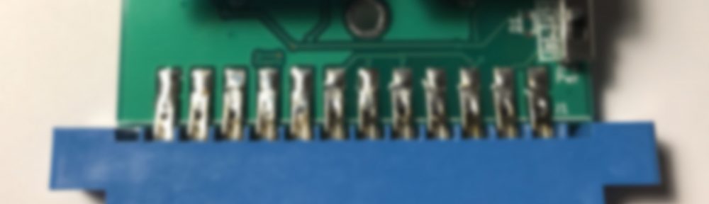
Using a perfboard and a couple of header connectors I whipped up a simple “shield” to terminate the ribbon cables and to connect them to the Rainbowduino. Also, there was enough space left on the board to hold the components used to convert the voltage levels of the serial connection between router and Rainbowduino. I already described this method in my last post. Strangely, this did not work without problems as it did in my test setup: Using my scope to measure the output, I could see clearly that the signal level was converted from 5V down to 3.3V by the voltage divider. When I connected the 3.3V output to the input line of the router though, the signal level dropped again, down to 1.6V. Too low for the router to read the signal. Lacking a good explanation, I decided to adjust the voltage divider accordingly – which solved the problem for me. (You can see the shortened resistor on one of the pictures.) If you know the reason for the additional voltage drop I’d really appreciate to hear it in the comments…
Firmware
This was the truly easy part! There is an awesome alternative firmware for the Rainbowduino available on Google Code called RainbowDashboard, featuring among other things a UART mode, additional commands, double-buffered graphics and a nice and clean code base. In other words: exactly what was needed for this project.
So far, I needed to make no more than two changes to the code. The first was to reverse the order of the LED columns. I seemed to somehow have wired the columns backwards. I could have re-wired the ribbon cable on the connector shield. But it was far easier to just reverse the order of the columns in the firmware.
The other addition I made was to solve a timing problem. The Rainbowduino takes no more than a second to “boot” after it is powered on. The RainbowDashboard will then readily read and accept commands from the serial interface. The router on the other hand needs more than 30 seconds to boot before I can configure it’s serial interface. It seems to generate a lot of line noise during that time which the Rainbowduino then tries to parse and execute. This resulted in random commands being executed and some of the noise being visualized on the LED display.
To prevent this, I modified the firmware to boot into standby mode first. It will then listen for a predefined character sequence before entering the regular command mode.
I used git svn clone to fork the firmware sources and pushed the code, including my changes, to a github repository. This should be well covered by the MIT License that the original code was published under and I hope the author does not mind.
Software
The next step will be to write the software for the OpenWRT router to actually control the display. I will cover this in part two, so stay tuned. It might take a while though, since I’m currently lacking the time to work on this project.


Pingback: OpenWRT and Scripting Languages on the TL-MR3220 (Part 1) | hackup.net