The original external power supply for the Commodore 64 comes in different forms but they all have one thing in common: With increasing age they are prone to failure and when they finally break they are likely to destroy the precious computer they were powering.
An original PSU for the Commodore 64.
The power brick for the Commodore delivers both 9V AC and 5V DC, the latter being produced from 9V AC with a voltage rectifier and a linear voltage regulator. While this voltage regulator is generally very reliable, it has to operate at the upper limit of its specification which takes its toll after decades of use. When the regulator finally breaks, it tends to short internally, thus supplying the sensitive TTL ICs inside the C64 with up to 9V instead of 5V since there is no integrated over-voltage protection.
There are different ways to prevent such damage. The power supply can be replaced with a modern, more reliable one. But suitable, high quality devices can be hard to get and quite expensive. The original PSU can be opened and retrofitted with a modern voltage regulator. But this is not as easy as it sounds as the internals of the power supply are cast in epoxy. And not everyone is comfortable tinkering with circuits connected to mains voltage.
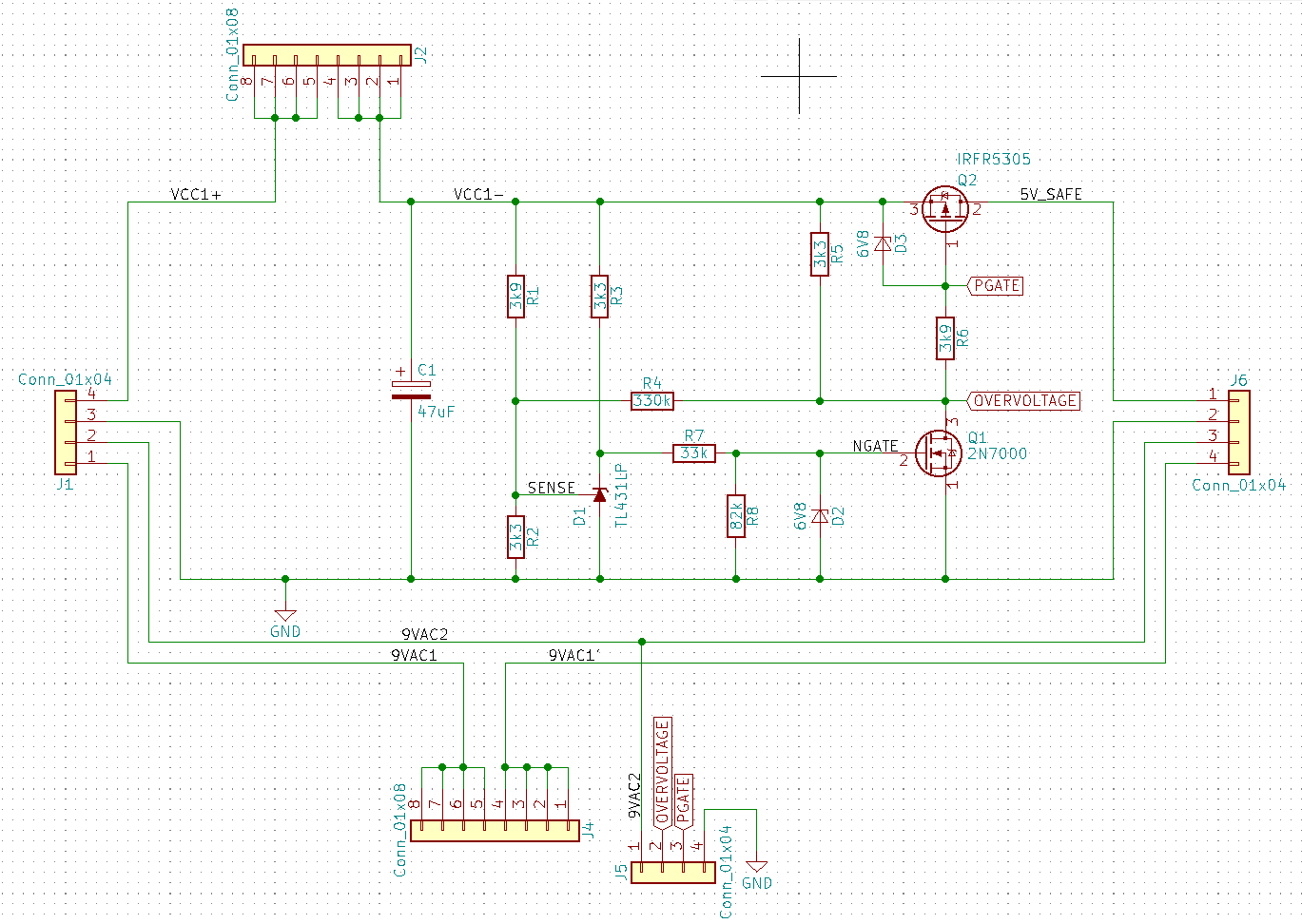
OpenC64Saver Schematics
The third solution is to add the missing over-voltage protection between the power supply and the C64. One way to do this would be a “crowbar” circuit that blows a fuse in case of an over-voltage. Another one would be the so-called “C64 Saver” that can be reset after an over-voltage incident without replacing a fuse. I believe it was Ray Carlsen who originally popularized this idea. But I first learned about this device in 2017 when Giorgioggì published his OpenC64Saver PCB layout of the circuit as open hardware and I stumbled across it in a post on Lemon64.
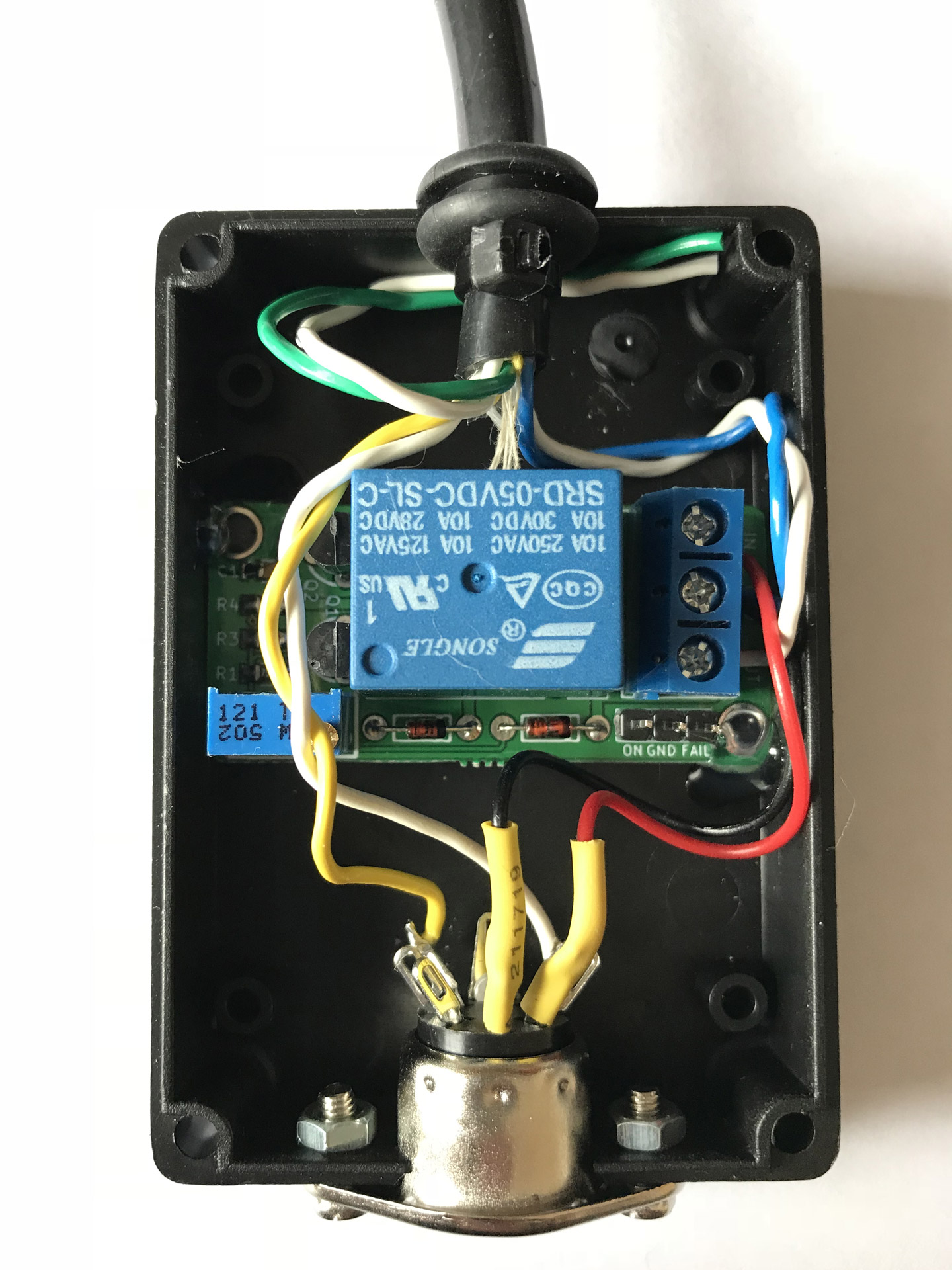
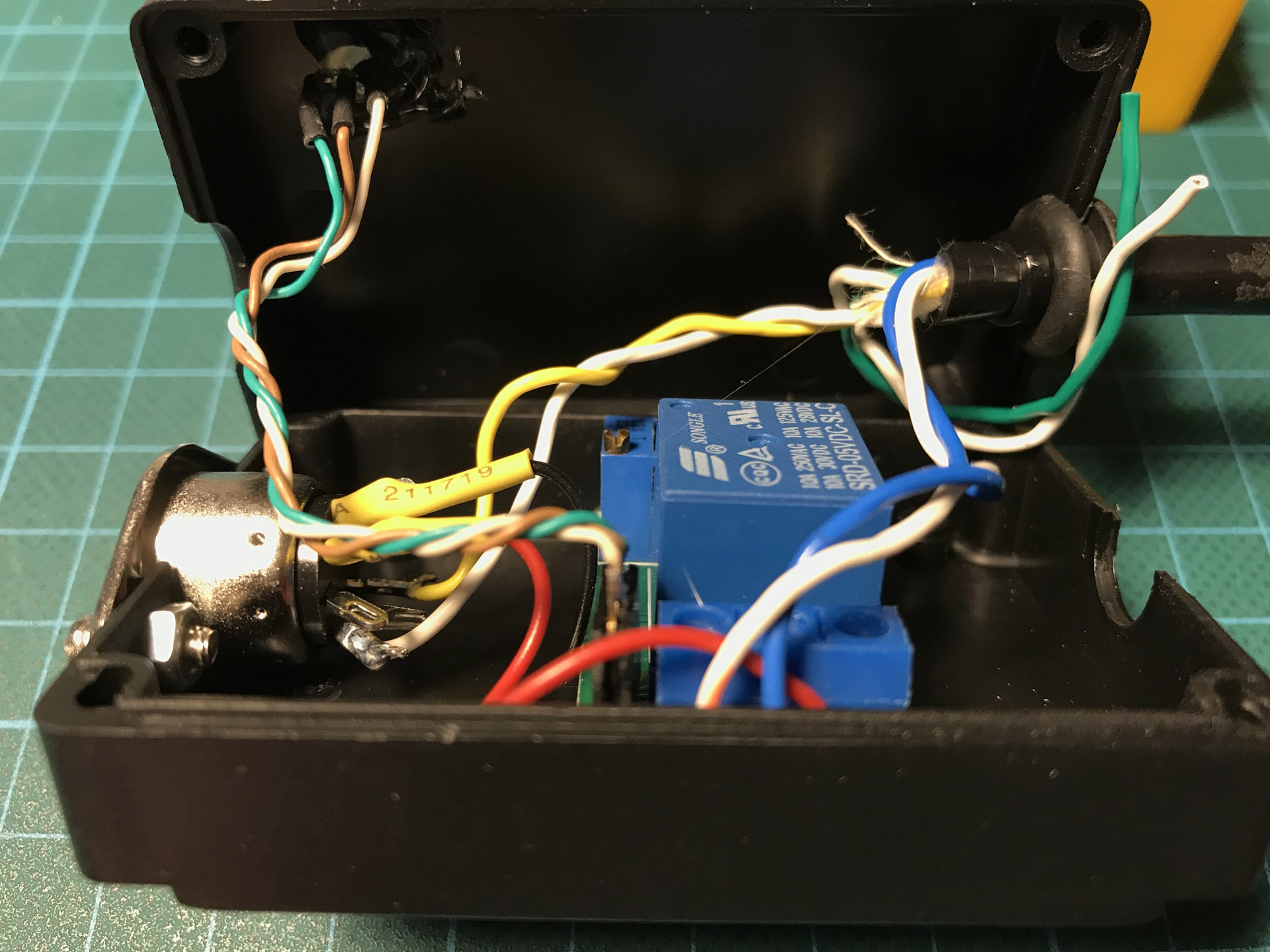
Inside the OpenC64Saver.
The C64 Saver circuit is actually quite simple. In short, it uses a Zener diode and a transistor to monitor the DC voltage from the power supply and a second transistor to drive a relay. A potentiometer is needed to calibrate the exact voltage threshold. When the input voltage rises beyond a certain threshold the relay cuts off the 5V rail. See Ray Carlsen’s documentation if you’d like to learn more.
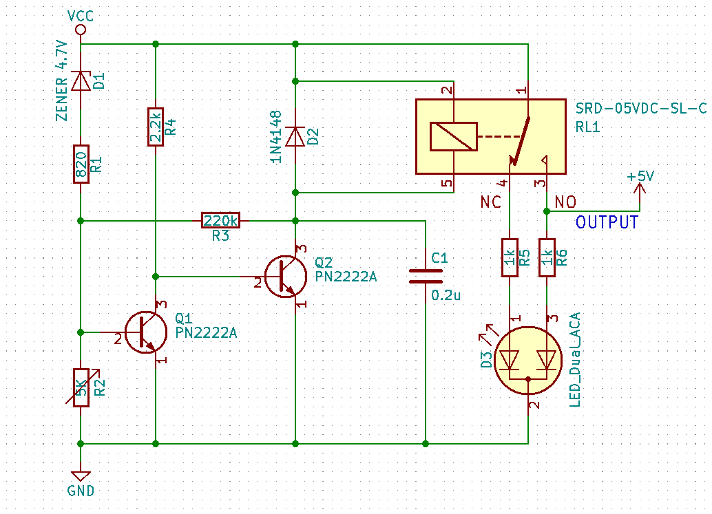
Bwack’s C64Saver v2.4 Schematics
In 2015 (I think), Bwack began to work on his own version of the C64 Saver. He documented the whole process in a long series of insightful videos. When version 1 of his device was completed — version 1.3 being the last of that kind so far — it promised a few improvements over the design described above:
- The Zener diode is replaced by a much more precise TL431 programmable voltage reference, thus eliminating the need for manual calibration.
- The relay would take approximately 4 ms to cut off power in case of an over-voltage. Bwack uses a power MOSFET instead to decrease this reaction time drastically.
- The version 1 PCBs are very compact and allow for creative ways to integrate the device. The last two minor versions even fit inside the DIN plug!
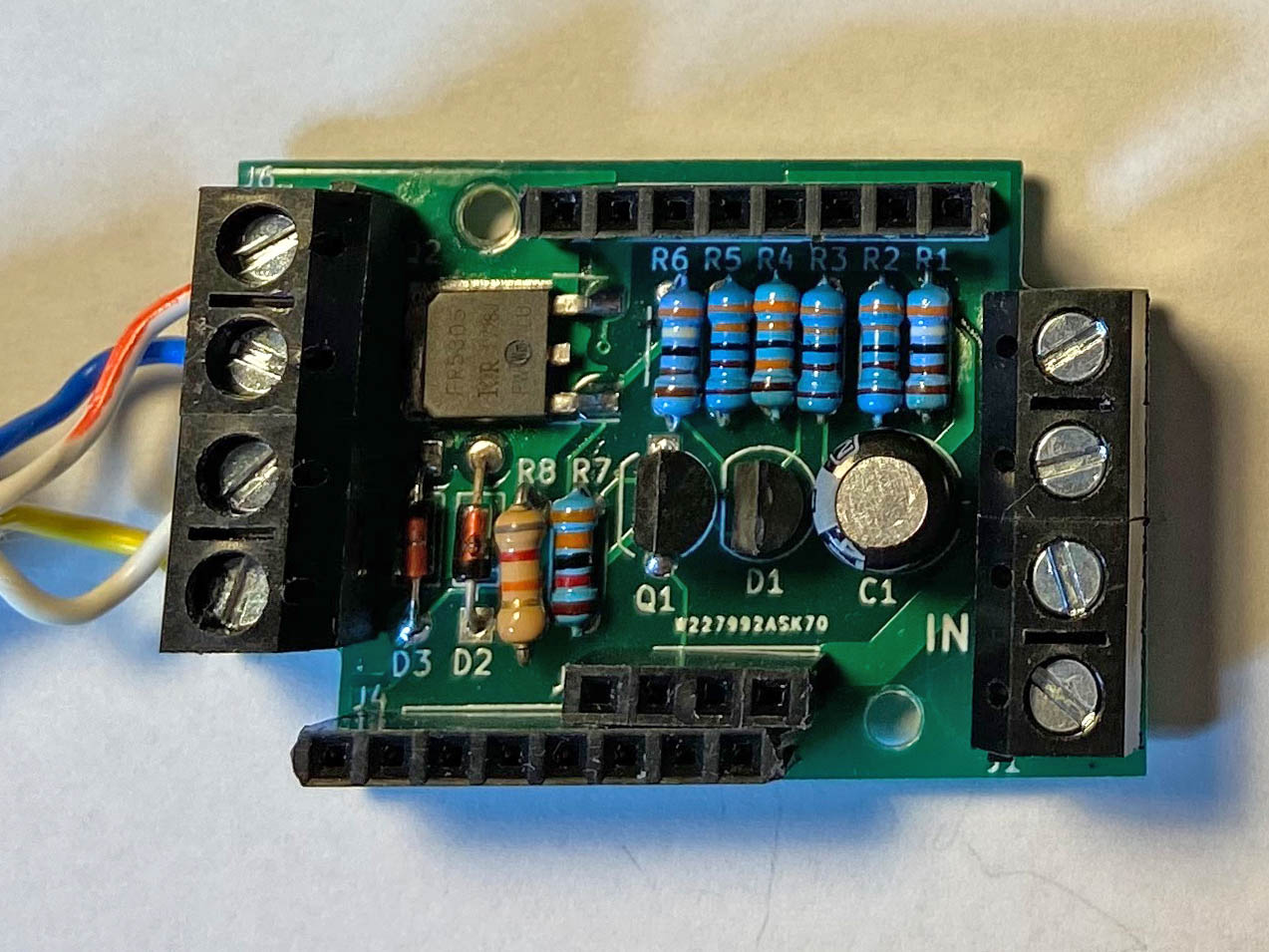
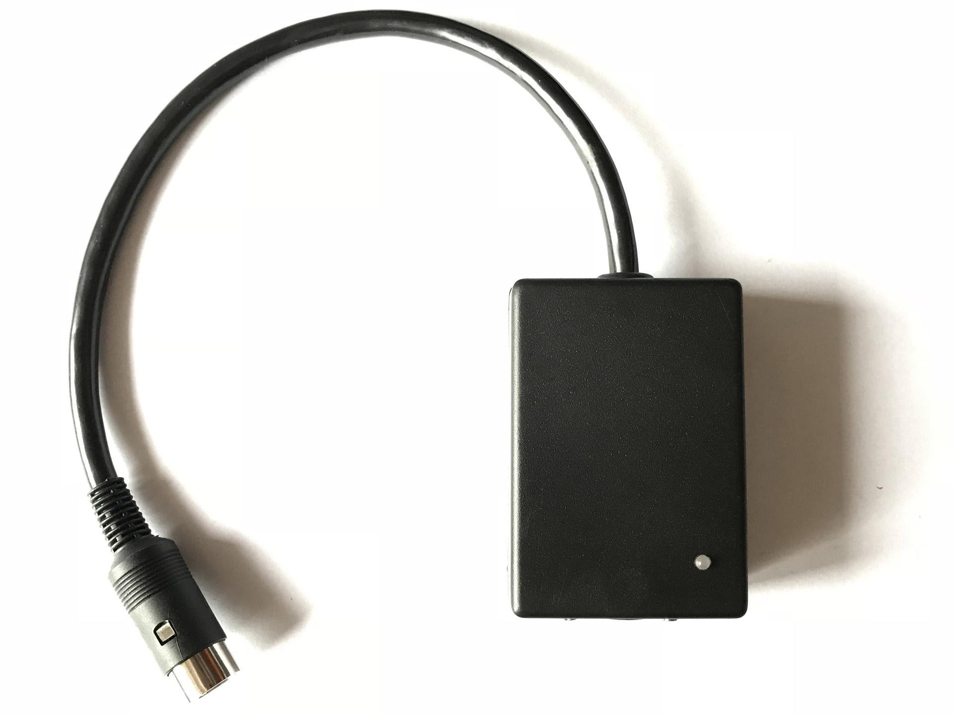
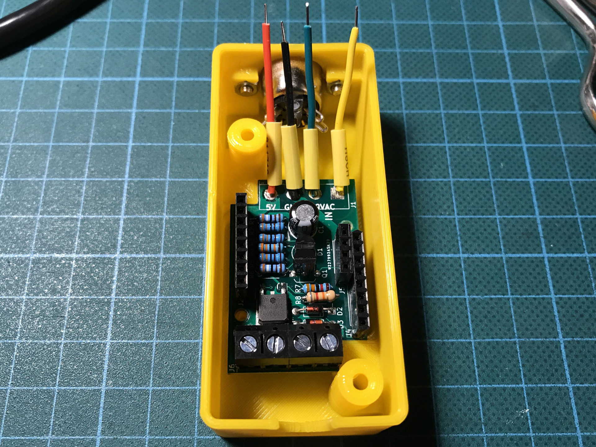
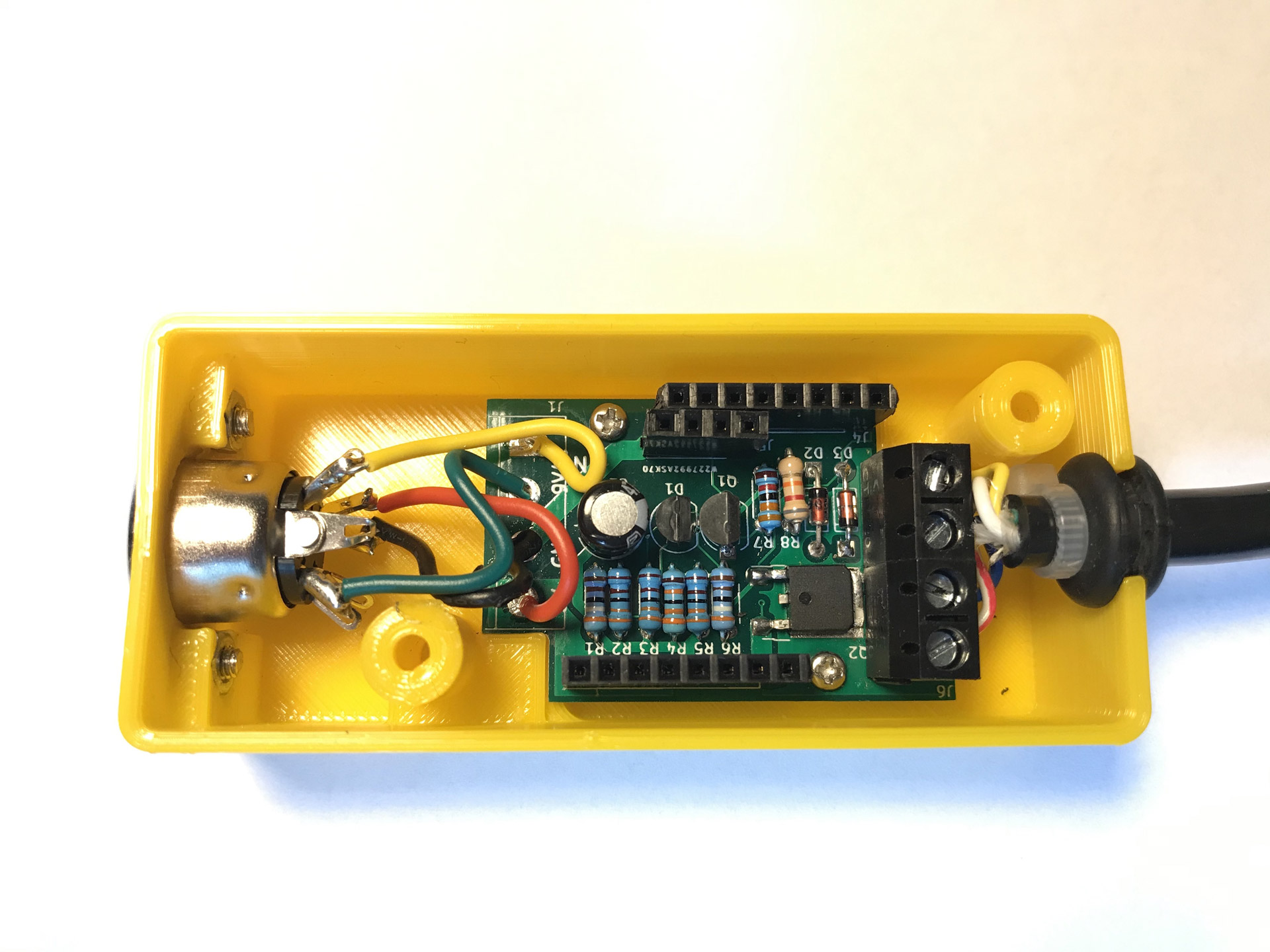
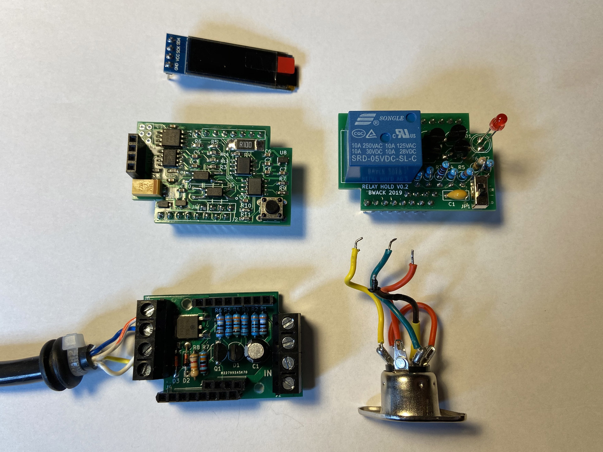
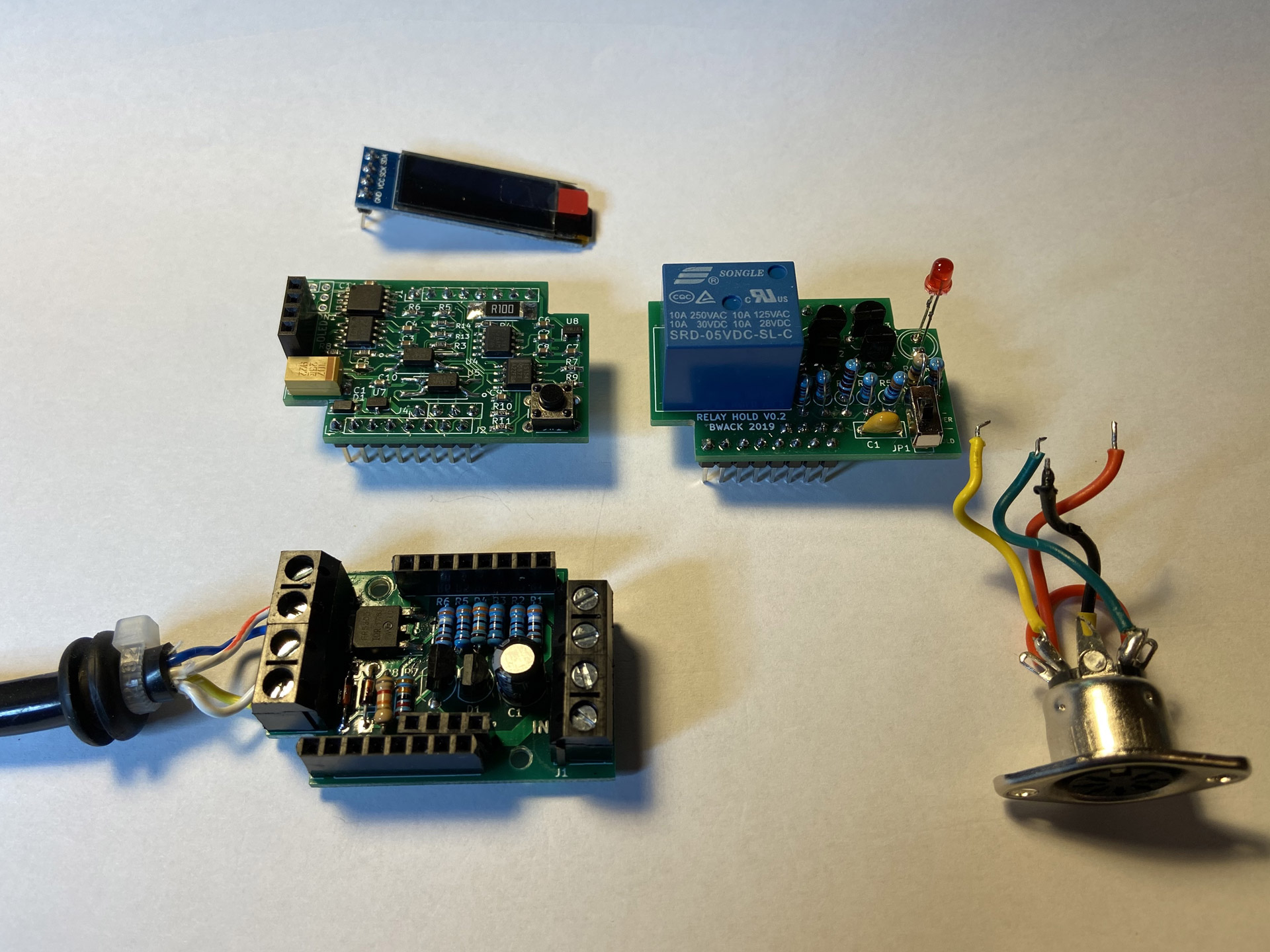
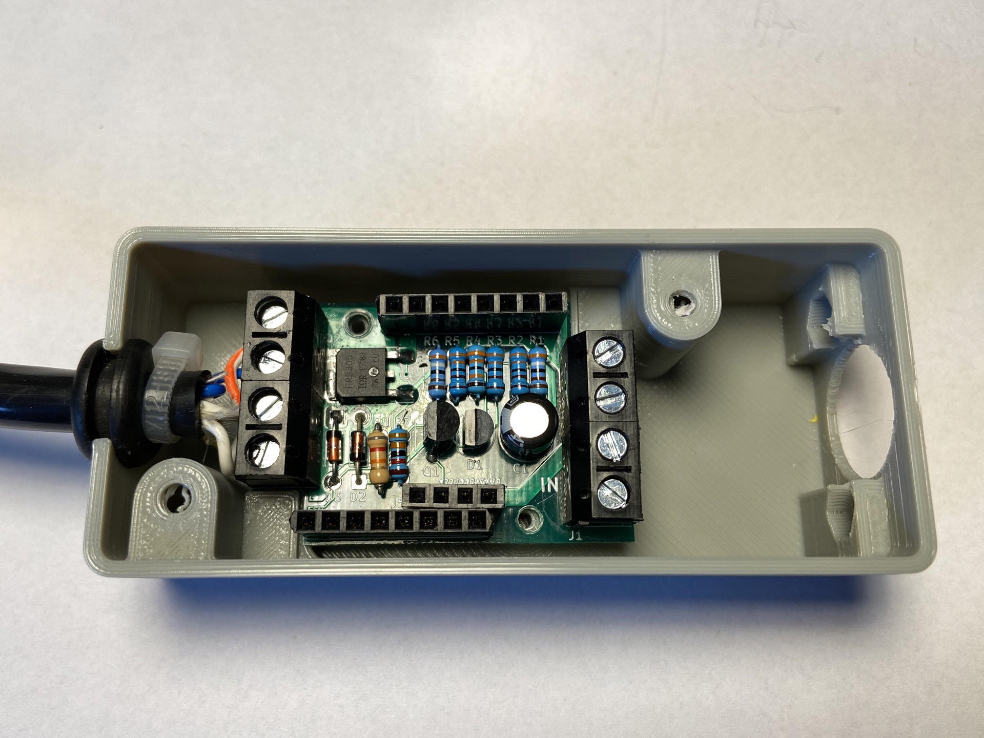
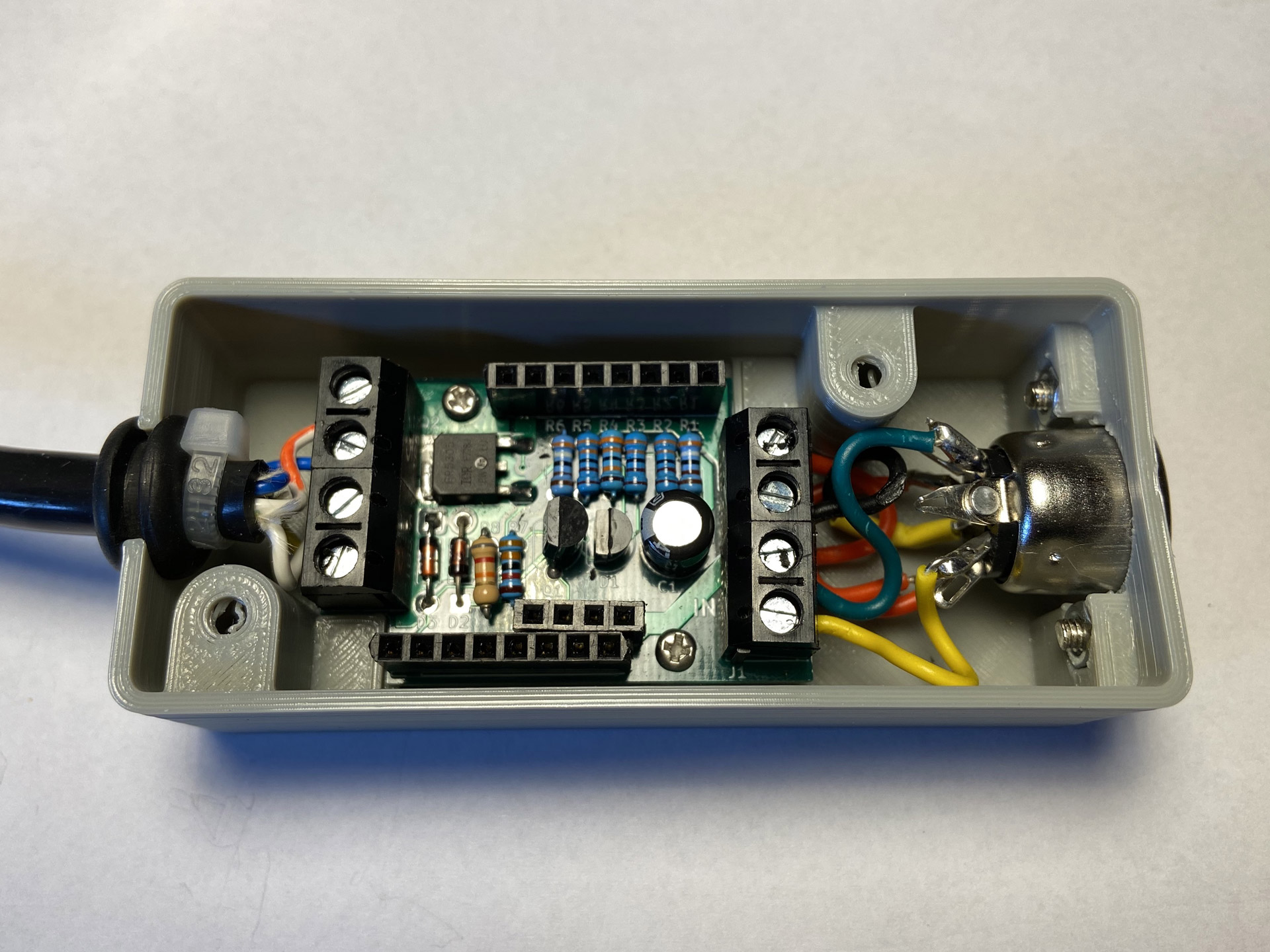
C64 Saver base board.
I haven’t built Bwack’s C64 Saver version 1 (I still might, though!) because before I got around to it he had released version 2. The advertised additional improvements are:
- A modular design.
- Spike protection and improved handling for hot-swapping and switch bounces.
- Supposedly easier to make, because the footprint increased again and mostly through-hole components are used.
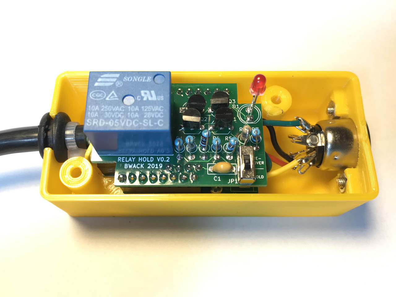
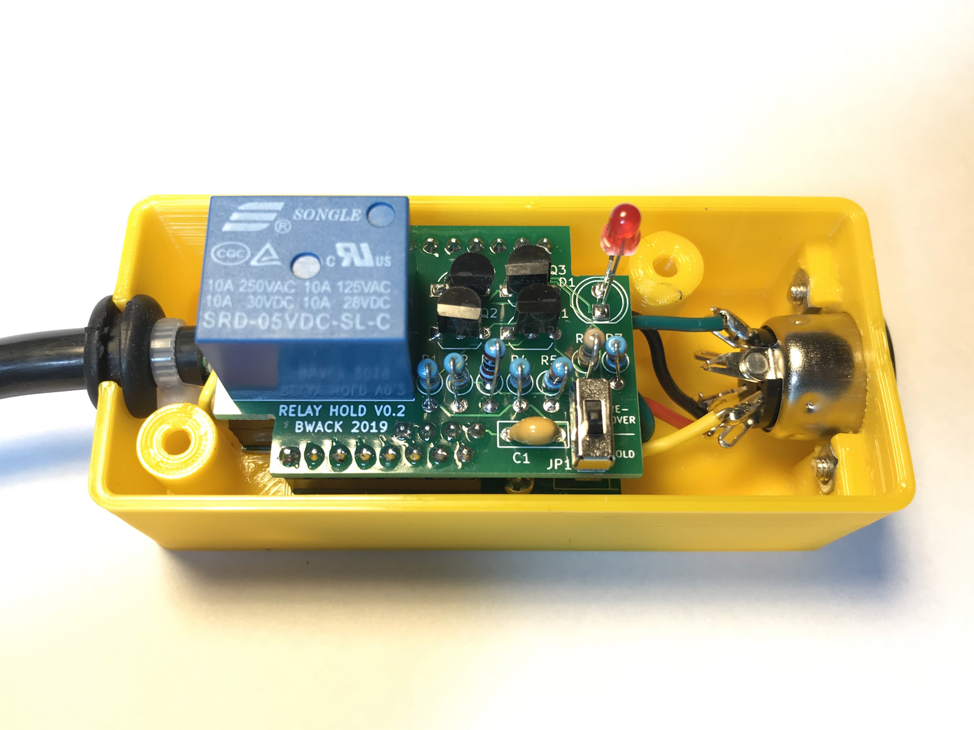
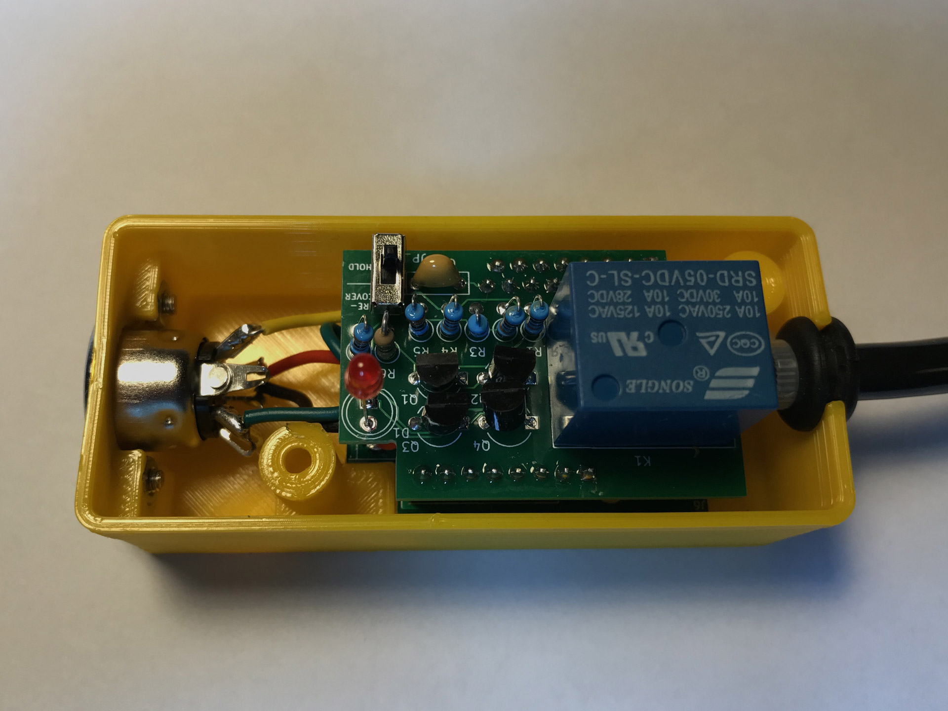
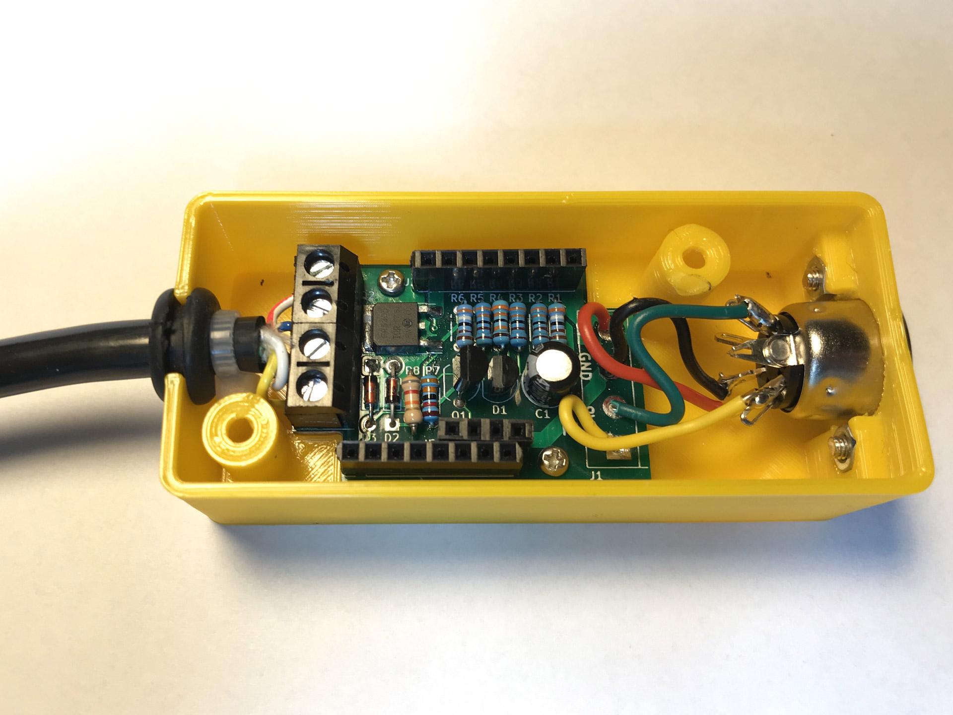
C64Saver v2 with relay holder board installed.
With the new modular design, the base board already delivers the functionality of the previous versions. To use the base board as a stand-alone saver the DC power rail on J2 has to be bridged and the AC rail on J4 respectively.
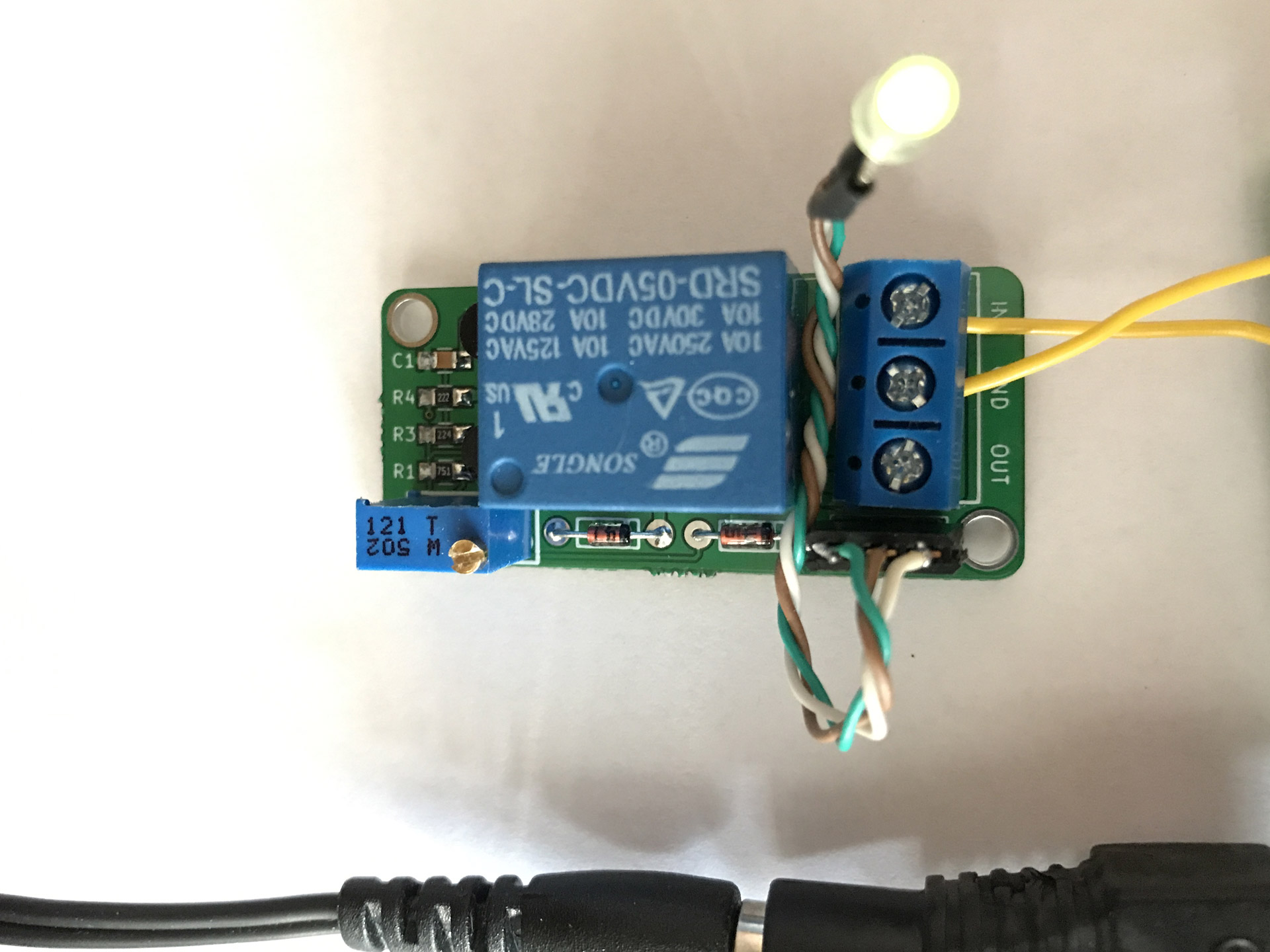
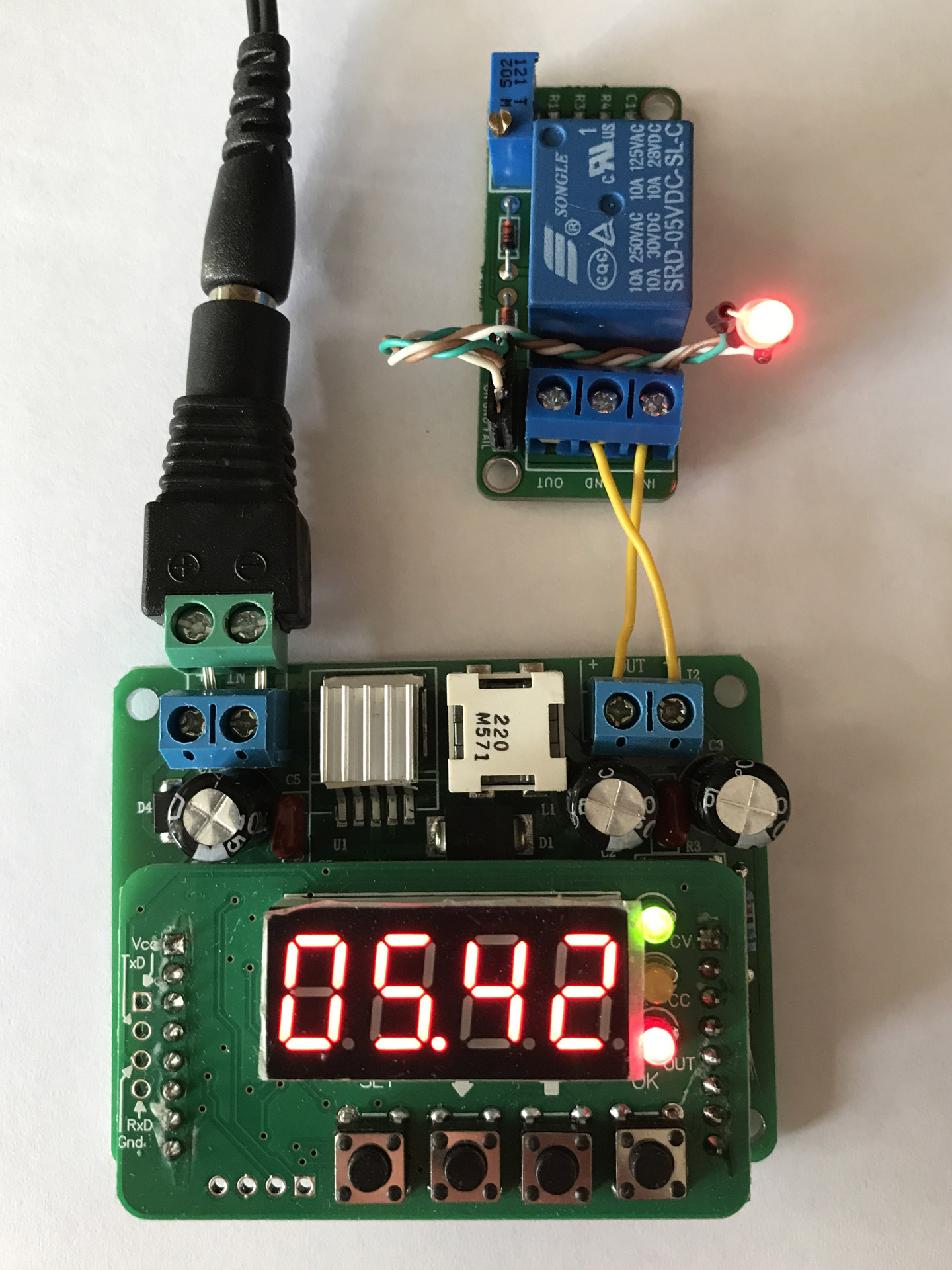
There are currently two different “hat” boards available, that plug into the base board. The simpler one is called the “relay hold board” and it features a relay that is used to also cut the 9V AC power rail when an over-voltage is detected on the 5V supply. Additionally, the relay board has an LED indicating over-voltage and a jumper that determines whether the saver will auto-recover as soon as the DC voltage drops below the threshold or only after being power-cycled.

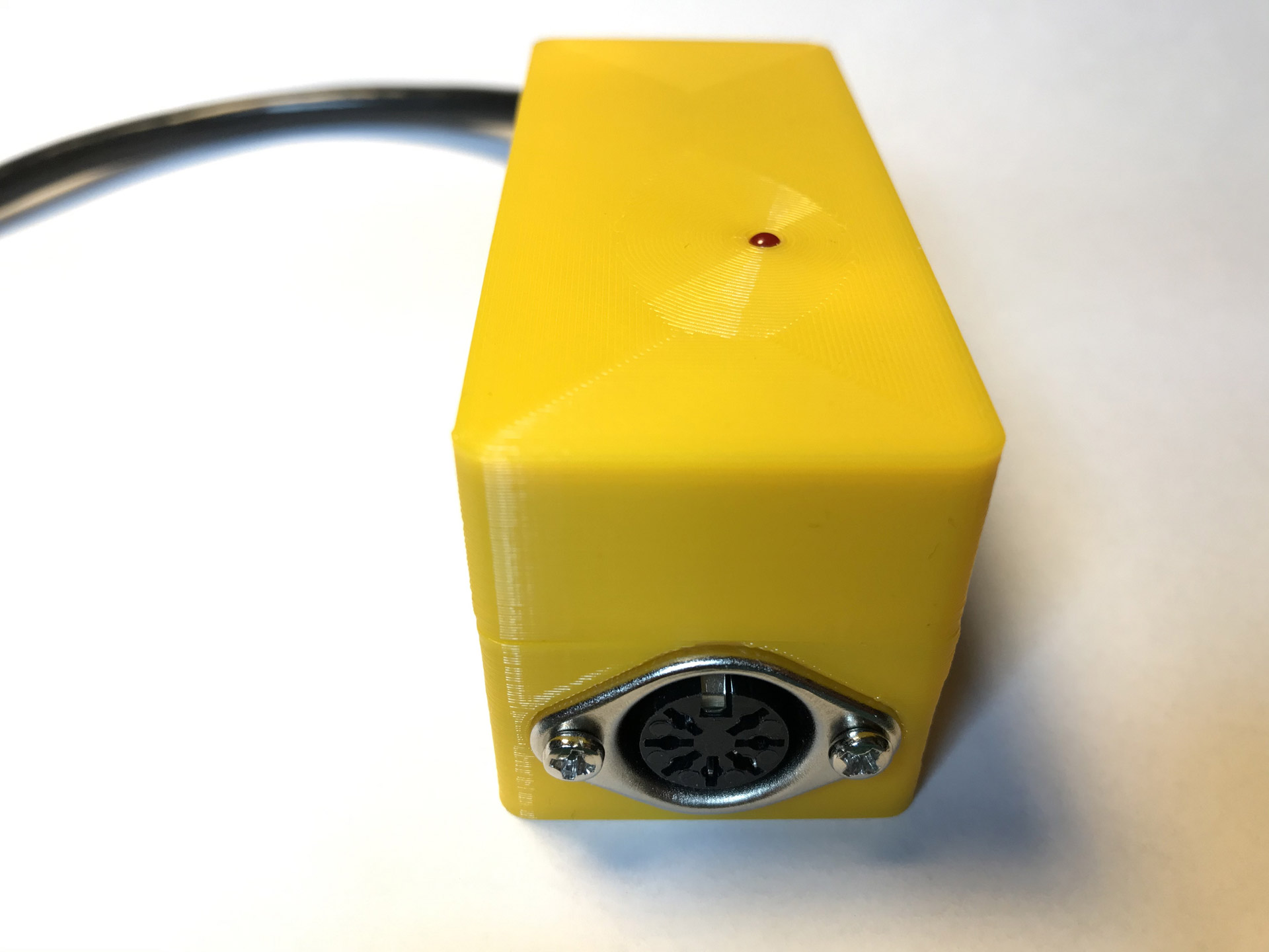
The completed C64 saver with a relay board and matching top part on the case.
The second hat board is simply called the “addon board” and it is much more sophisticated, harder to build and way more expensive. But it adds nice features to the C64 Saver that could be especially handy for those trying to repair broken Commodores:
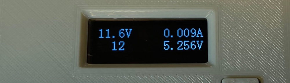
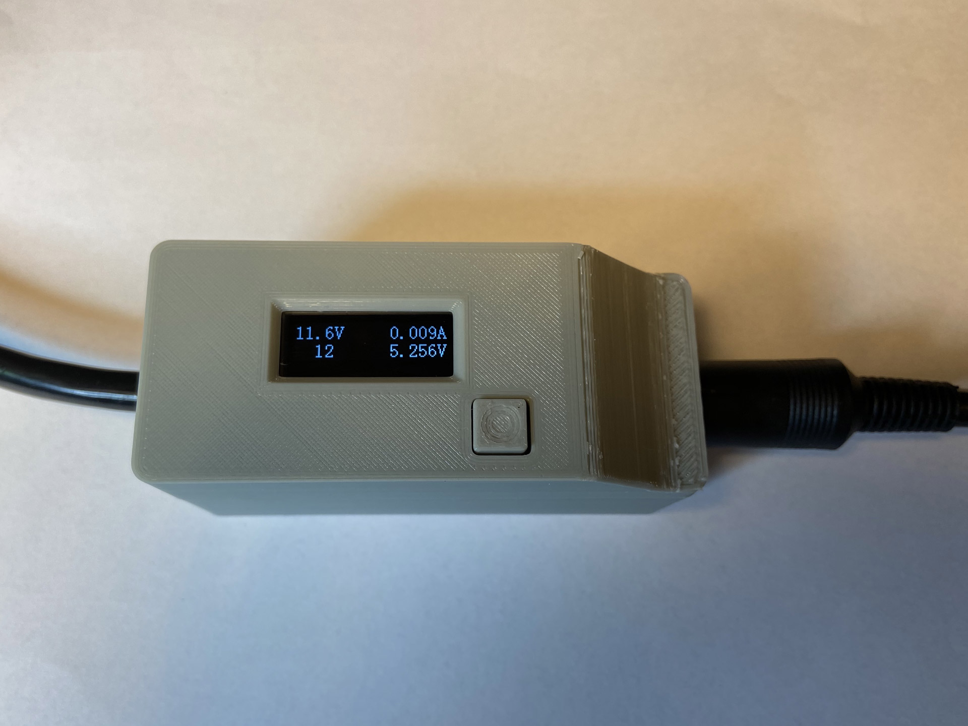
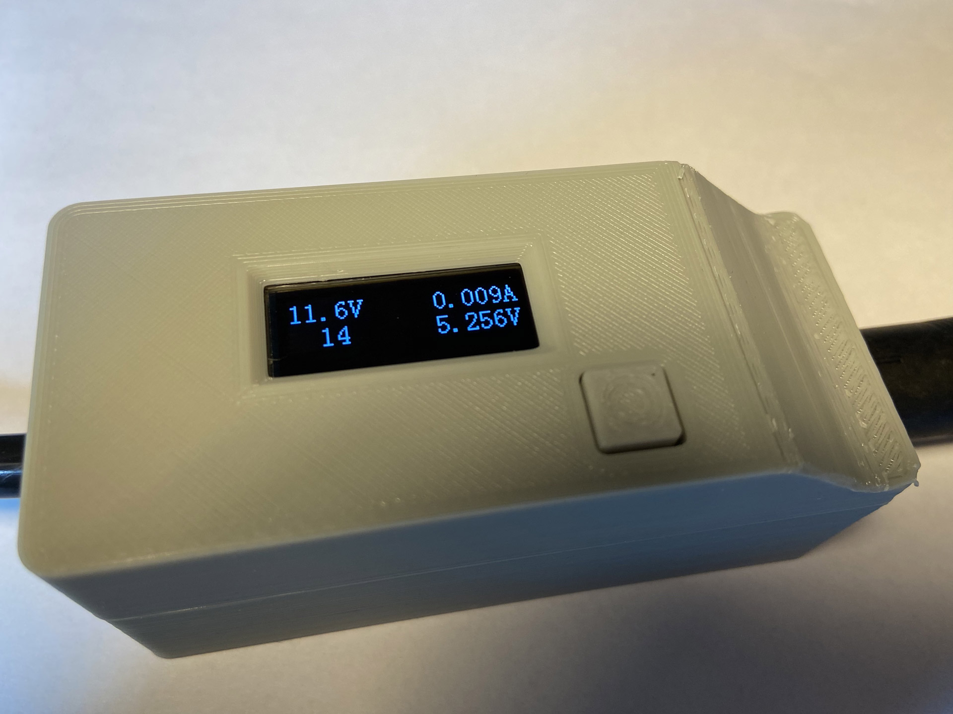
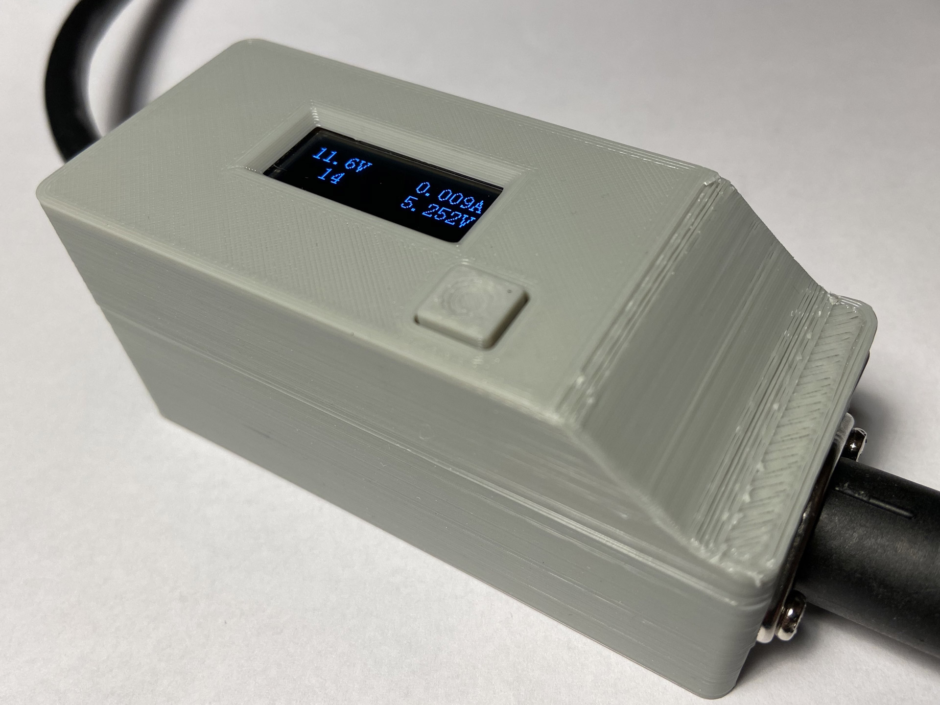
- Instrumentation to actually measure voltage and current on both the DC and AC rail.
- An OLED to display the measured values and user definable settings.
- Software controlled detection of over-current conditions with power shut-down threshold.
- Additional voltage threshold and auto-recovery configurable over the menu.
- A microcontroller to drive all of this.
- Galvanic isolation of the addon components from the saver circuit.
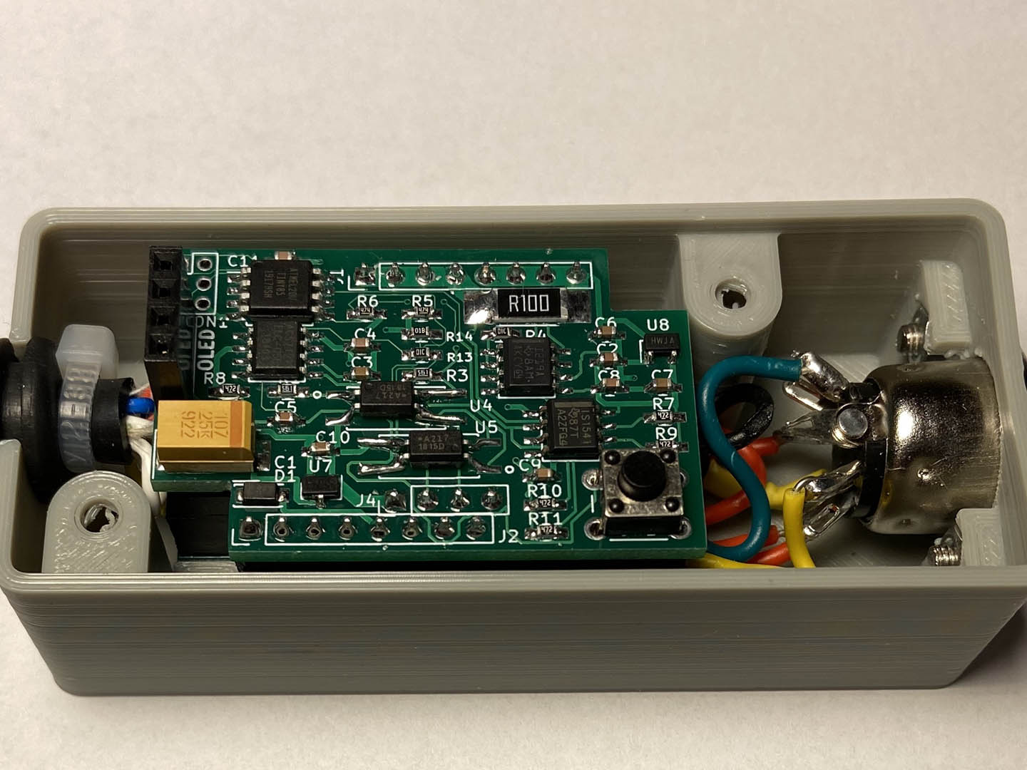
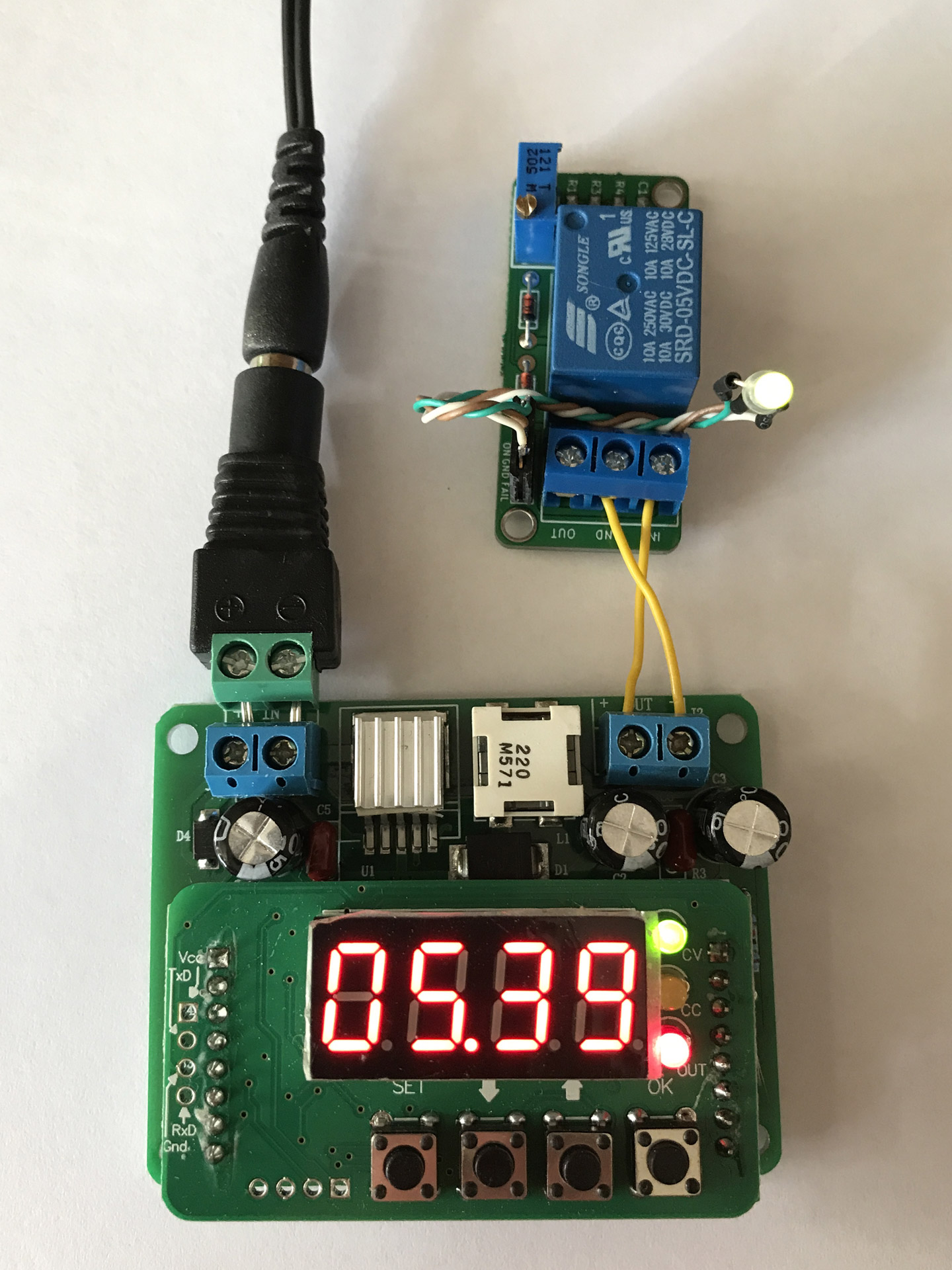
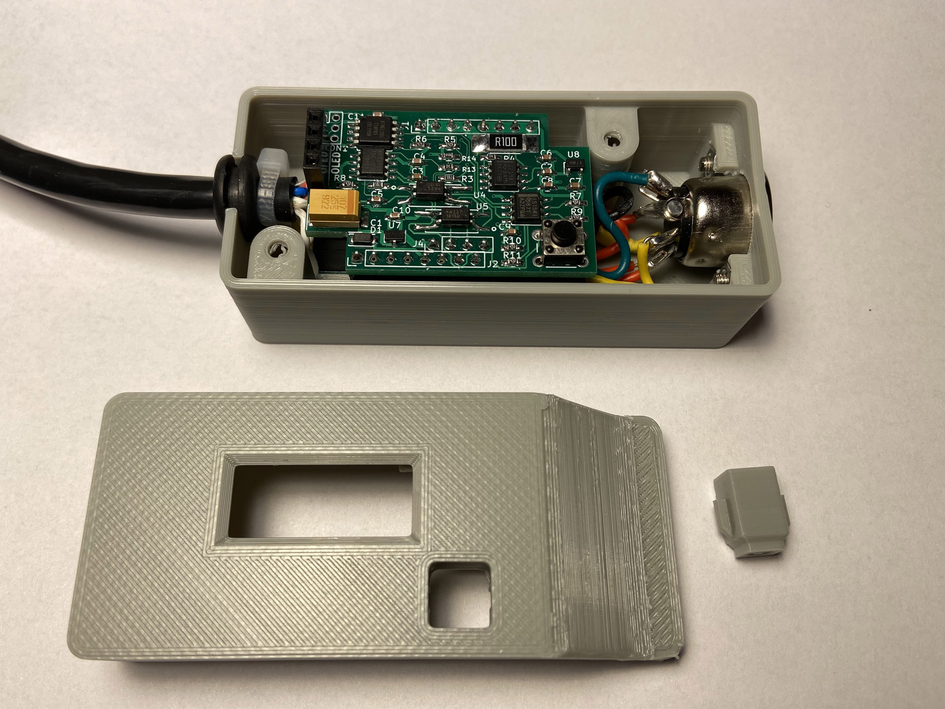
C64Saver v2 with addon board installed. (Note the improvised leads on the optocouplers needed to make them fit the PCB.)
When building the addon board, I had PCBs made for the latest release version 1.2 but I accidentally ordered components from the BOM found on the master branch of the repository, not realizing at the time that those two versions differ. So I had to improvise a little when I assembled the board. The package of the optocouplers for example did not match the footprint on the PCB. Still, everything worked fine when the board was completed.
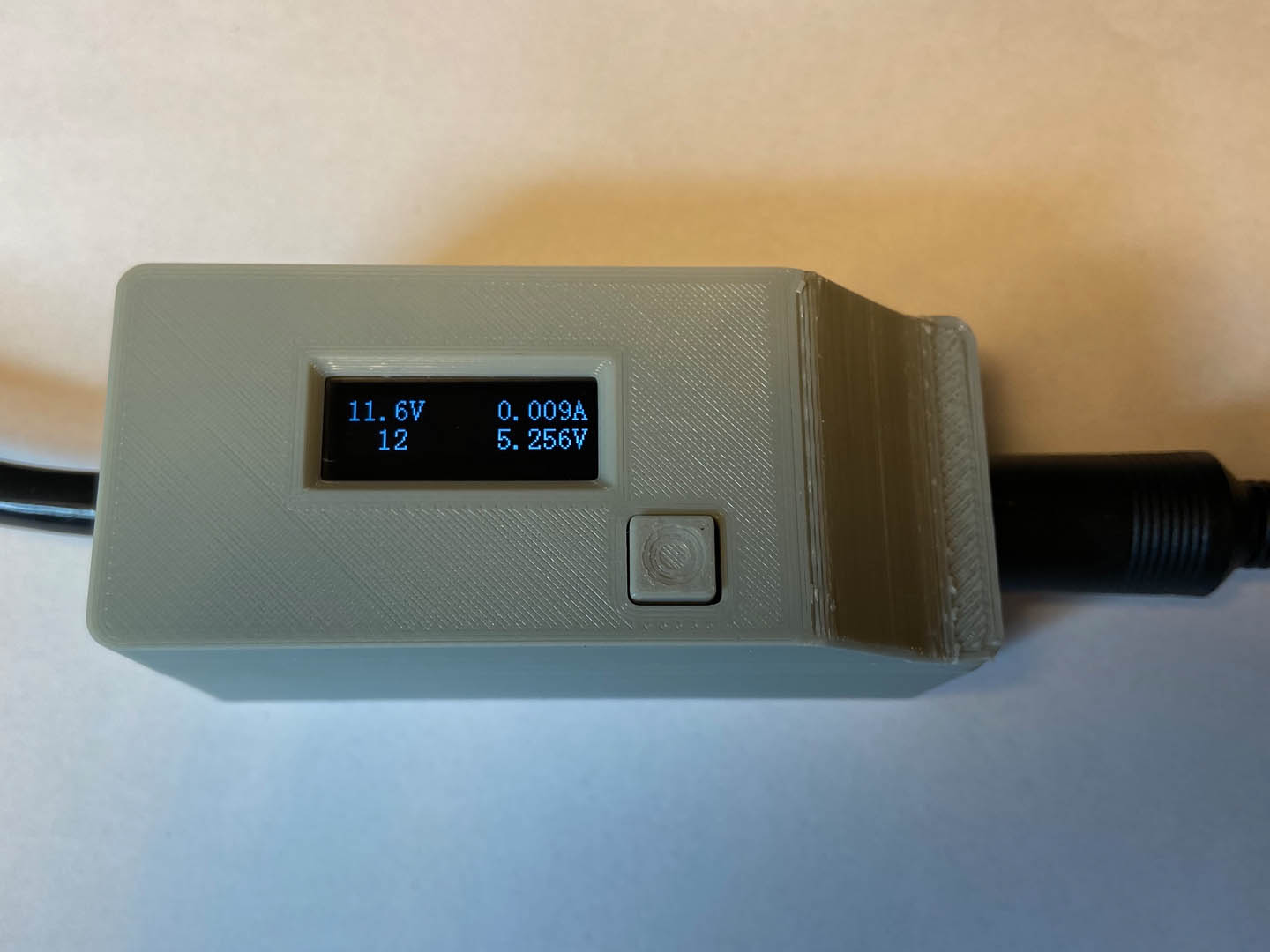
The complete C64 Saver v2 with addon board, display, and case.
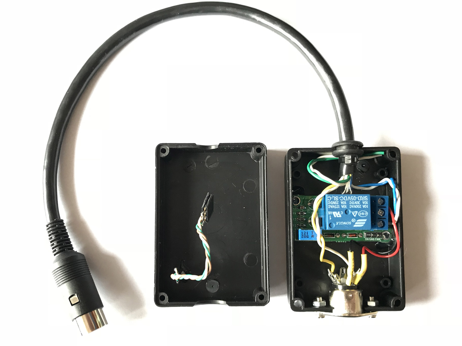
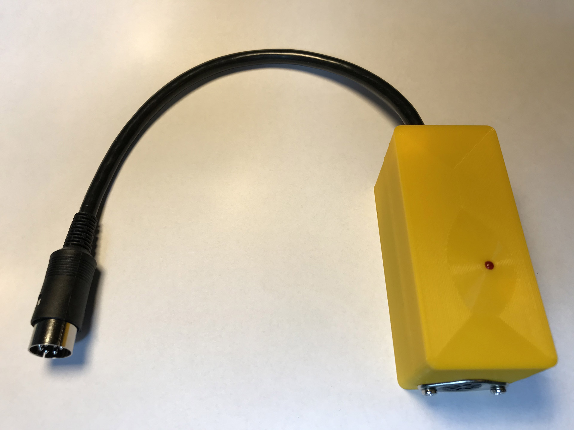
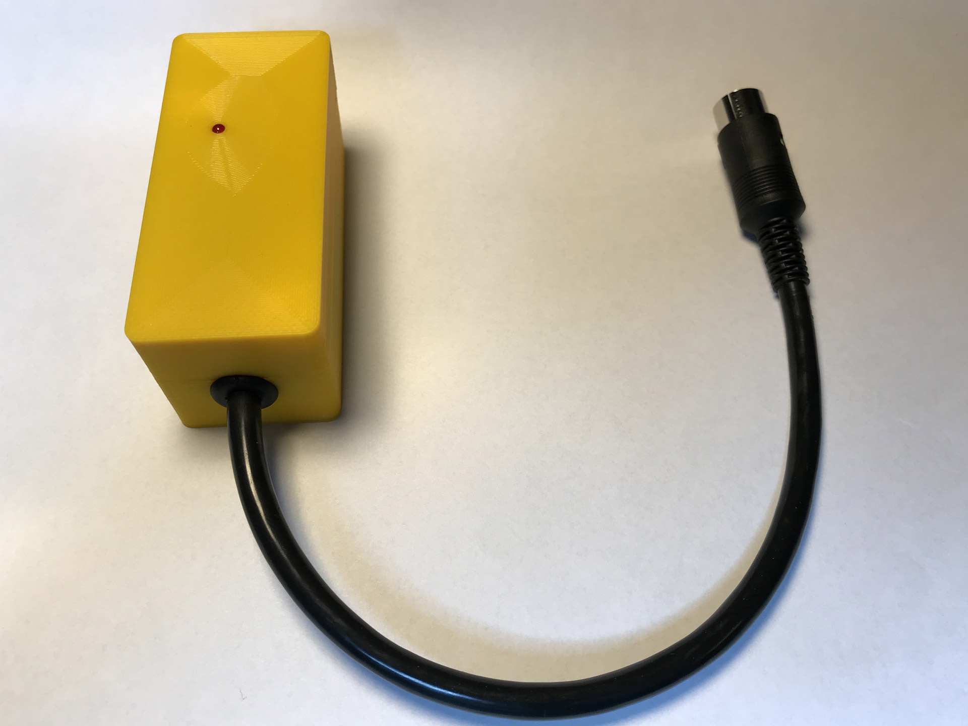
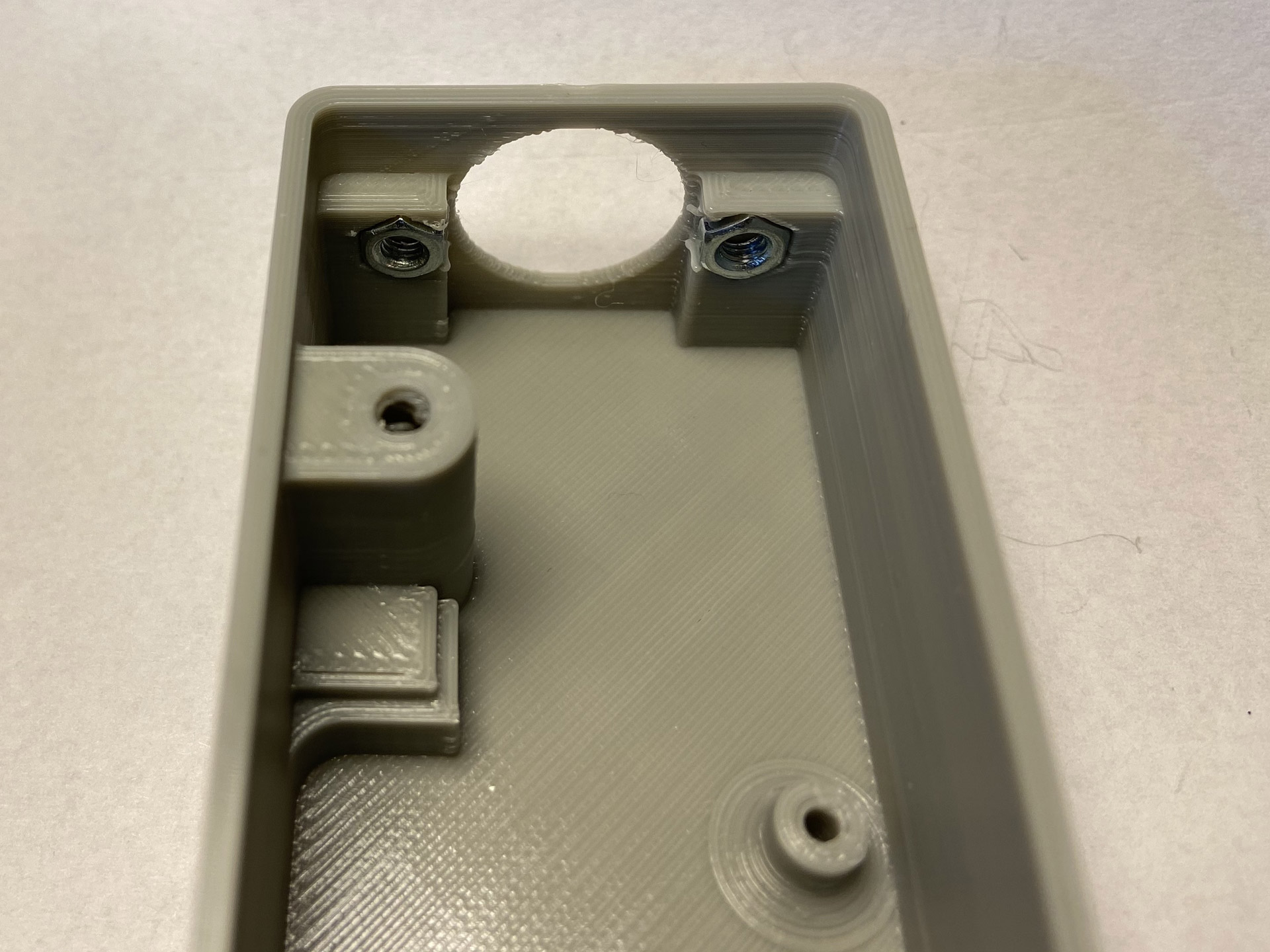
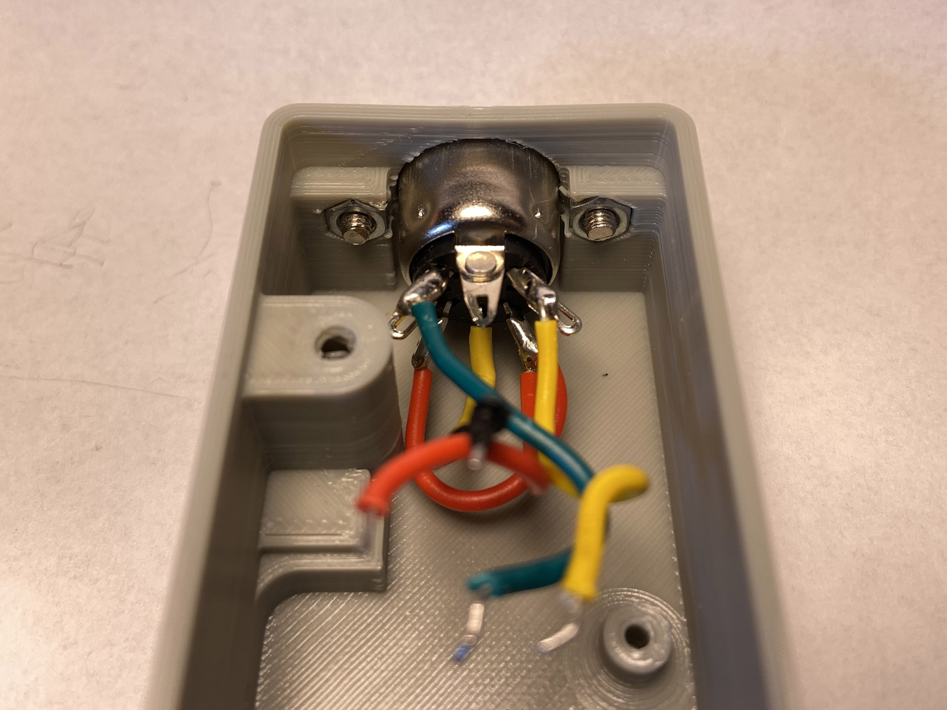
Finally, I created a matching case for 3D printing to house Bwack’s C64 Saver. The bottom part of the case holds the base board, the DIN socket, and it has an opening for the output power cable. Staying true to the modular nature of this version of the C64 Saver, there are three different top parts for the case that all fit the bottom part:
- A low-profile top for use without a hat board.
- One to accommodate the “relay hold” board and its LED.
- One for the “addon board” with an opening for the display and a plunger for the push button.
The STL files for the case are available on Thingiverse for those who would like to print their own.
Finally, just to be clear, none of this is my work except for the printable case. I’d like to say a big thank you to Ray Carlsen, Giorgioggì, and Bwack for sharing their respective projects!

Excellent project. I am a big fan of bwack’s many retro computer projects. I just completed a YT video hopefully helping novice makers to build their own C64 Saver V2.4. I hope to do the add-on board next. It is great to see that you have the add-on board up and running too.? Also, thanks for posting the case STL files — I guess I need to get myself a 3D printer now.
Is the saver solution much safer than taking the 9VAC and sending it through a rectifier and a 2€ DC-DC step-down module and sending it forward to the C64 along with the original 9VAC?
I’m not tinkering with vintage computers but I’ve enjoyed your blog post and the technical solutions. Regarding your case design: I’d like to encourage you to not only share the STL files. From my point of view it’s very valuable to have (ideally) access to the original 3D-CAD files and STEP-files too. The last one is a great exchange format across “all” 3D-CAD solutions.