
Last Summer, after a delay of mere 38 years, I finally acquired my first Commodore VIC-20, or VC 20 as it was called in Germany. Not all parts of the machine are in their original state as the connoisseur will notice on first sight. I don’t care too much about that because I didn’t want it as a collector’s item but as a technical gadget to play around with.
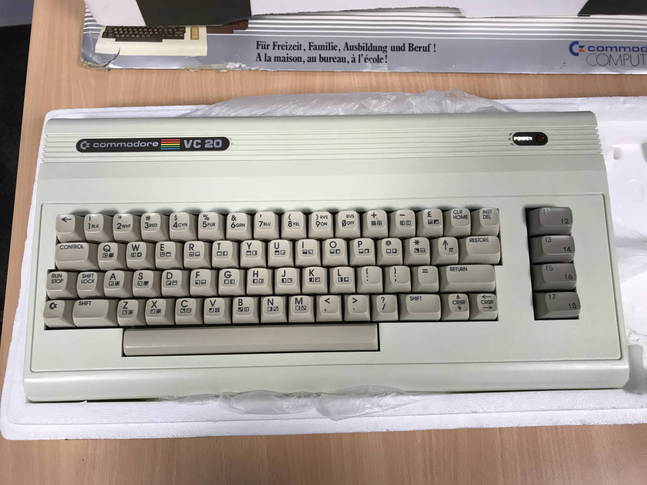
My first VIC-20, freshly supplied with a donor keyboard.
First thing I had to do to even test the machine was to make a new video cable to connect it to a monitor. The pin-out of the A/V jack differs from that of the C64: there is a Vcc output where the luminance signal should be and there is no S-Video output.
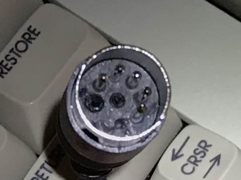
Video connector modified for the VIC-20
When I had finished the cable and hooked up the VIC-20 to the composite input of my small flat-screen TV, I was shocked. Knowing the composite video from my C64, I hadn’t expected too much from the video quality. But the picture that greeted me was far worse than I had feared. The Basic prompt was just barely recognizable. It was actually hard to capture on photo how bad it really was. For some reason, most of the photos look even better than the real thing.
I asked for advice on Forum64 and learned that the video quality of the VIC is generally below that of the VIC-II and also that it tends to vary between individual machines. The only way to improve quality seemed to be modifying the VIC-20 for S-Video output, losing the composite signal in the process.
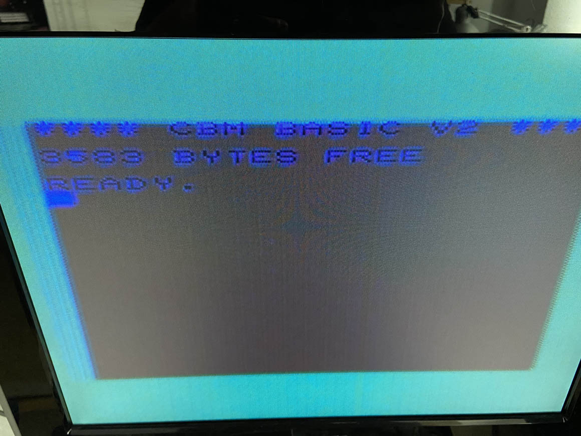
My first impression of the VIC-20 video quality
At that point I wasn’t quite ready to permanently modify my VIC-20 and fancied an adapter board between the VIC chip and it’s socket that would satisfy all of the following requirements:
- Plug-and-play. Just pull the VIC out, insert the board instead and plug the VIC into the board.
- Easily reversible. Restoring the original state of the VIC-20 should be just as easy as installing the board.
- Both S-Video and composite. The composite signal should be provided as well, ideally improved at least to the level of a C64.
- Easy access. The video signals should be routed out of the case in a robust and elegant way. Ideally with a pin-out fully compatible to that of the C64.

First feeble prototyping attempt
Unfortunately, even after quite some time of thinking about this I couldn’t come up with a way to fully satisfy all of the above criteria. On top of that, another factor eroded my motivation for this project: I knew the difference in quality between composite and S-Video from my C64, and while it is still considerable on that machine, the same level of improvement applied to the VIC-20 would probably still not result in a video signal I’d find usable. Oh, how wrong I was.
All of this lead to my VIC-20 just lying around for 7 months and gathering dust in a corner of my workshop. A few weeks ago, I finally acknowledged that I would not build my “perfect adapter board” anytime soon. The only realistic way to get the VIC-20 into a usable condition would be to modify the mainboard after all.
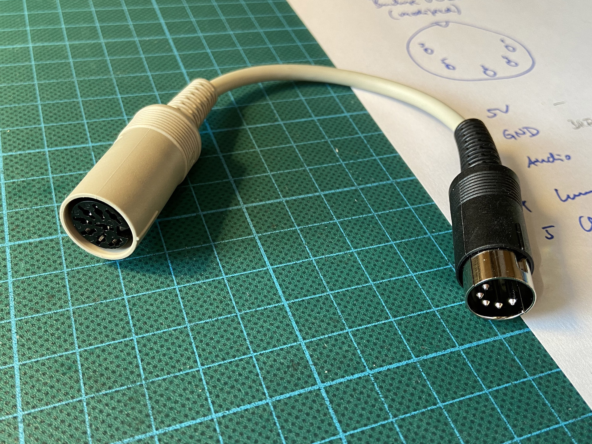
Adapter cable needed for the modified video jack
So, I set out and followed these instructions that would remove the composite signal from the video jack and replace it with luma (Y) on pin 4 and chroma (C) on pin 5. The hardest part for me was cutting those two traces on the old PCB. It almost caused me physical pain when I did. But to cut this long story short: when I connected the modified board using the newly created adapter cable I was simply blown away by the result!
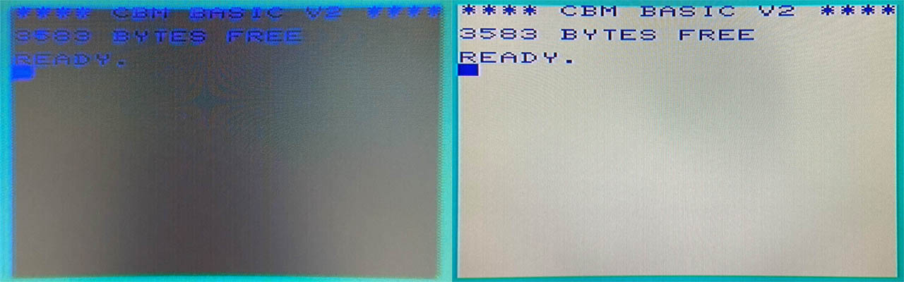
Basic prompt before and after the mod
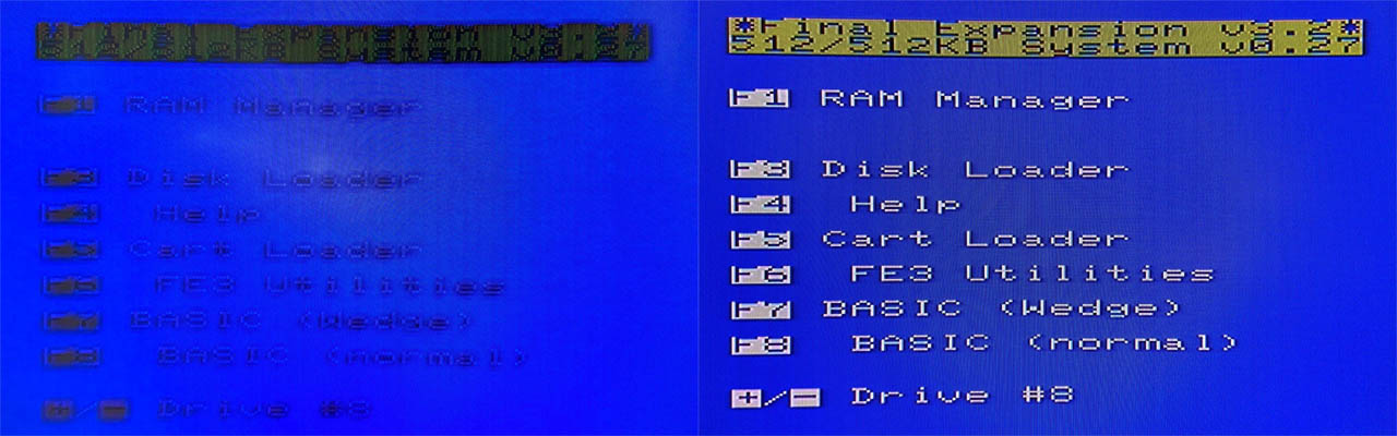
Menu of the Final Expansion 3 before and after the mod
Again, it was surprisingly hard to properly capture the difference with a camera. The video quality went from “damn-near-unusable” straight to “crisp-and-clear”. The difference was orders of magnitude beyond anything I had seen on a C64 when switching to S-Video.
I still feel some regret that I had to modify the mainboard to achieve this and I would sill love to see a video jack fully compatible to the C64 with an improved composite signal. For me tough, this mod was totally worth it.
Meanwhile, Kinzi has resumed work on an adapter board where I gave up. His solution does not satisfy all of the criteria specified above but it certainly is a step in that direction. I might post an update here when I get the chance to try it out myself.
The Photo Story
The instructions for the mod found on Sleepingelephant are really good. If you intend to try it yourself, you should go and must definitely read them first! To supplement them, I’d like to share the pictures I took during the process because they might make it even easier to follow along.
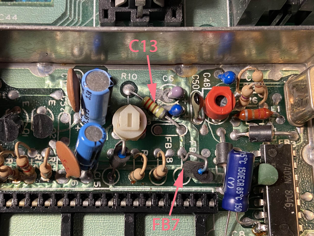
We need to desolder and remove C13 and FB7.
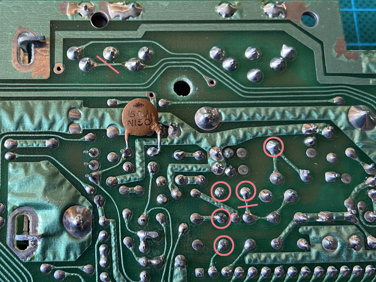
To do so, desolder five connections marked with a circle and cut two traces.
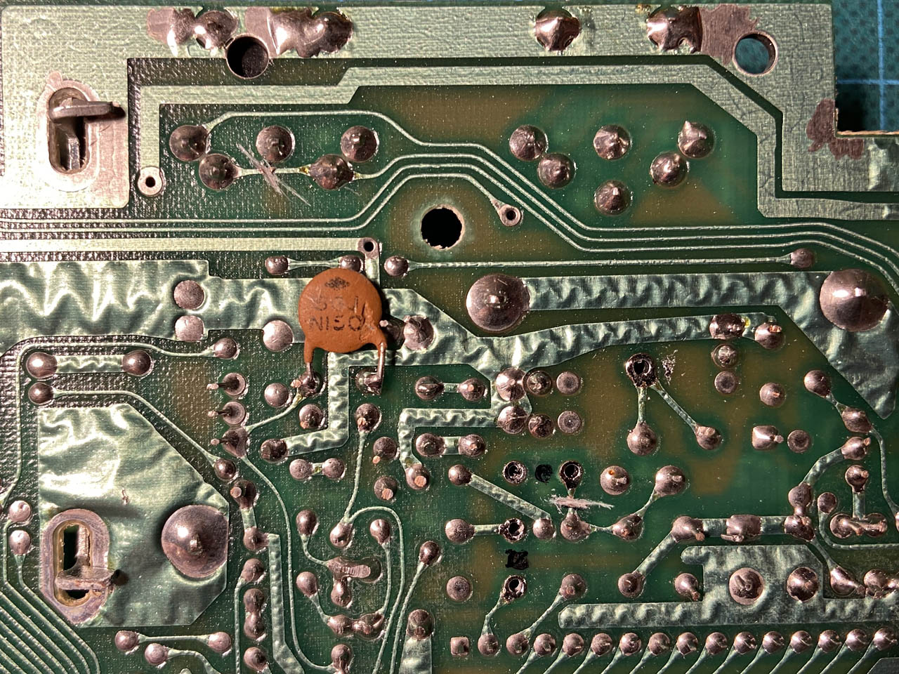
This is how the board should look like on the bottom after it has been thus mutilated…
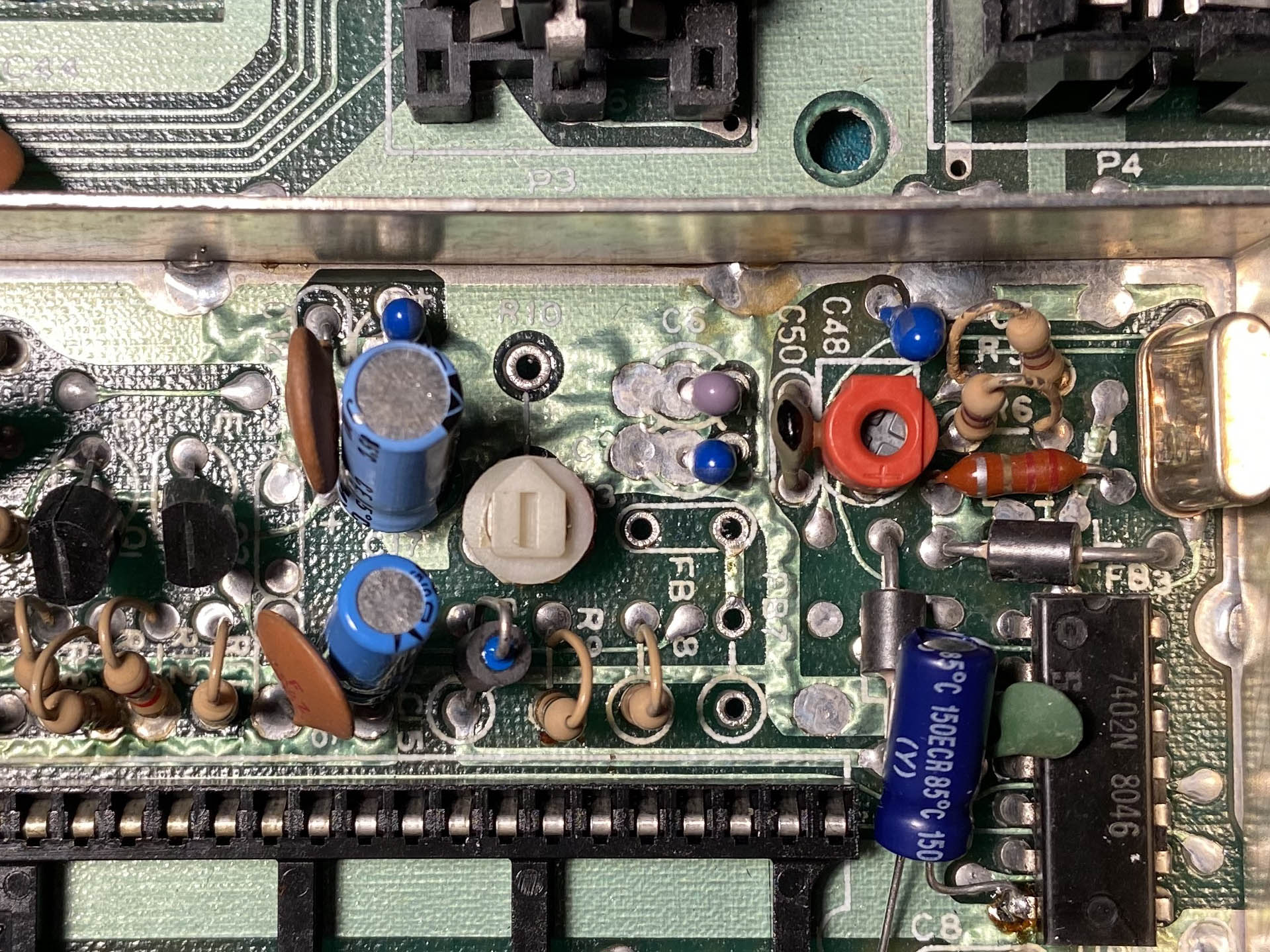
… and this is the top side with C13 and FB7 removed.
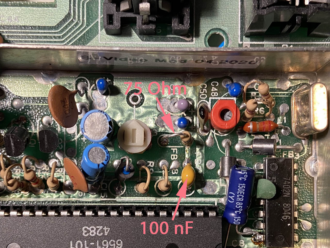
Add a 100nF capacitor and a 75Ohm resistor like so.
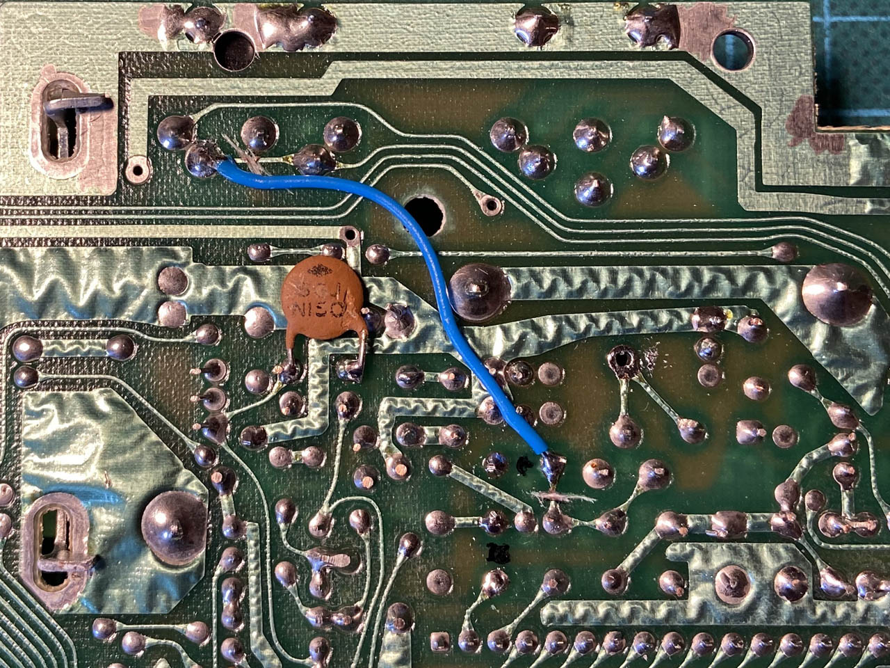
Finally, solder the botch wire to the bottom of the board.


Something must had been incorrect before you did the mod. Sure, there are some severe dot crawl on an unmodified VIC 20, but the monochrome part of the picture is generally rather good.
Most likely the trim pot for video level was set incorrectly.
Hello, I agree with the comment above, the VIC20 S-Video mod that you have used on various websites and forums on this subject are now obsolete and inappropriate.
It uses keep the original Composite signal from the VIC20 which just needs to be enhanced (“cleaned up” and amplified).
To do this, from the start you must not touch anything on the motherboard (nothing to unsolder, nothing to remove).
You simply have to separate the 6561 video circuit board from the VIC20 from its socket to connect it again to a CLEAR VIDEO PCB.
The interest of this CLEAR VIDEO mod is to allow the processing, “cleaning/filtering” and amplification of the composite video signal from its source (6561 video printed circuit).
The value of the potentiometer you are going to adjust (modify) on the original video part of the Vic20 will normally become useless.
With this CLEAR VIDEO device you will have the choice of either using a Composite or S-Video (RGB) signal.
To switch to a Composite signal, you will need to add a 100 pico Faraday polypropylene capacitor between the two Chroma and Luma terminals on the CLEAR VIDEO device in order to mix Chroma and Luma again.
Without this 100 pico Faraday capacitor, you will have S-Video (Chroma and Luma).
In my opinion, the Composite signal is much better suited for the vast majority of TV screens.😉
Sincerely
Thankyou to the anon ^ above- because there are NO schematics for the Clear Video MOD board for the 6561 VIC chip anywhere! the etsy seller provided NO schematic or more than handwritten, mildly vague instructions. I lost the tiny cap he included when opening the package, so the value of 100pF here is valuable, just need to know how to wire this up: sounds like cut the traces? or leads to the DIN, and wire directly from the board, using the non polarized cap between chroma and luma pins on board? *nothing* should be this hard to figure out, lol, in this day and age- !