When I discovered the MMC2IEC / SD2IEC project by chance back in 2009, it made me dig up again my soldering iron and electronic components after many years of disuse. I built myself one of those devices on a prototyping board and had a lot of fun doing so. It was the first time that I got involved with micro controllers and I learned a lot in the process.
Now, many years and projects later, I was looking for an excuse to try out KiCAD and to learn how to design my own boards using it. I had already ordered a small PCB I found on the net as a proof-of-concept to see if the Gerber files I produce would result in working boards. When they turned out just as expected I was eager to create something myself. This was the perfect opportunity to revisit the subject and make myself a brand new SD2IEC.
I wanted the design to be based on Shadowolf’s latest version but also make my own additions and changes:
- The board should be able to tap into the cassette port of the C64 for power supply.
- It should be board for external use with proper connectors just like my first build.
- All components should be cheap to buy from Chinese suppliers.
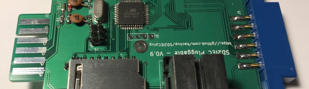
So, this is the first prototype of what I came up with. I call it the “SD2IEC pluggable”:

On one side, it plugs into the cassette port, but all lines are traced across the board to the other side. This should allow the use of a datasette without unplugging the device. I haven’t tried it yet because I currently don’t have a datasette available. IEC and SD connectors are facing left as is the USB connector serving as an optional external power source. It is currently mini rather than micro USB because that was what I had in stock.
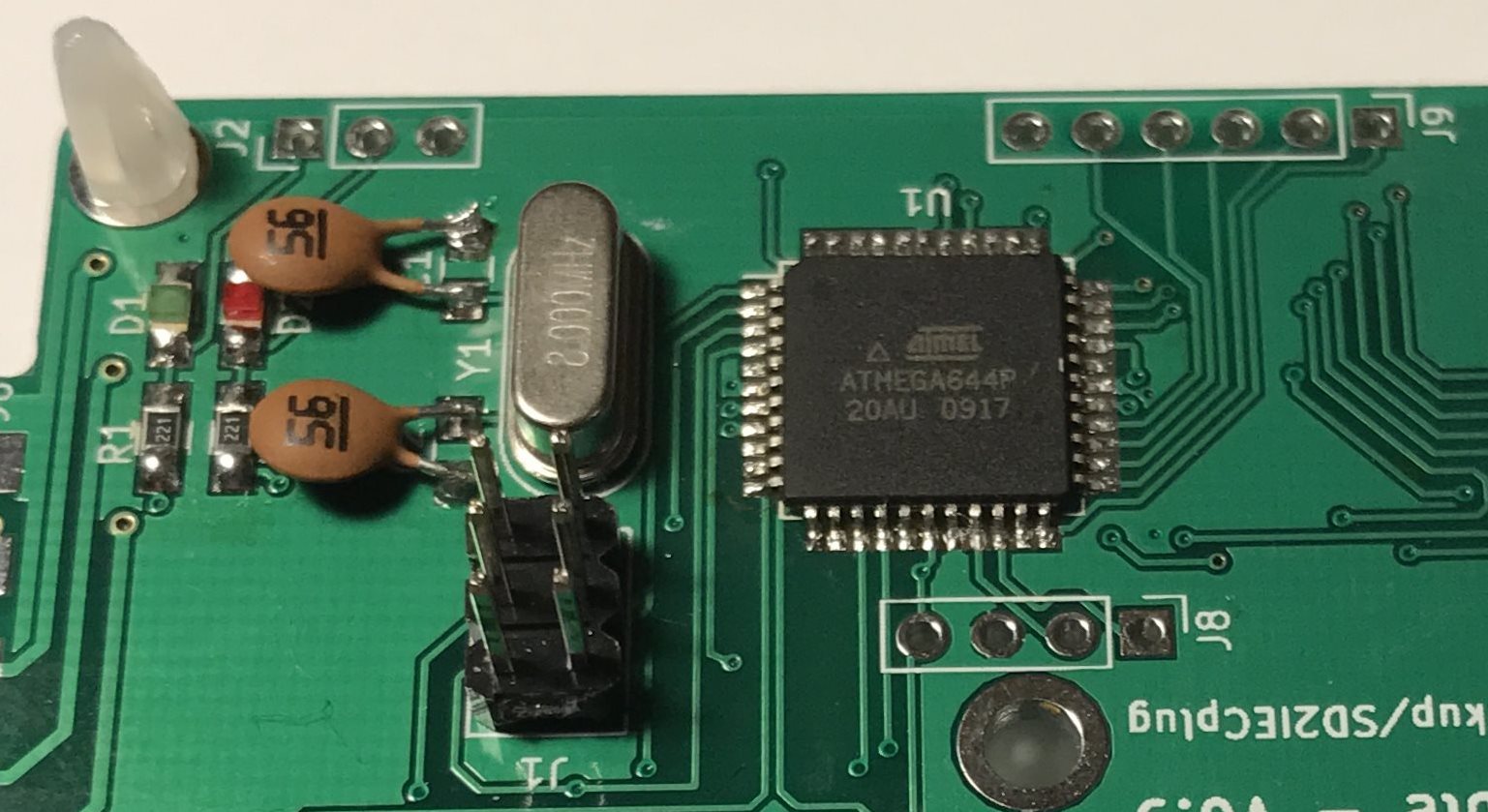
There are pin headers for the ISP, for connecting alternate LEDs, for I2C devices (like displays) and for optional buttons or switches. Also optionally, additional components can be fitted that should hopefully allow turning this board into a TAPuino using the right firmware. But I did not yet have time to try this either.
I just assembled the first board, flashed the latest SD2IEC firmware, and it seems to be working great! There are a few issues in version 0.9 that I’m planning to resolve in the next revision:
- Pin 5 of the USB connector needs to be connected to GND, too.
- Change footprint of D3 to accommodate MELF packages.
- Maybe replace the mini USB connector with a micro USB one.
- Add a reset button.
The KiCAD project files are available on Github in case you’d like to make your own pluggable SD2IEC. If you do, I would love to hear about it in the comments!


LOL, I just found this and then understood who you are! 😀 Well done, I’ll surely try it one day, keep it up!
Pingback: SD2IECplug v2.0 | hackup.net
Looks very interesting, I will try to check if I can update the circuit to ATmega 1284 and some other things like LCD connectors and then order some pcbs for my one. Great post, lovin’ it!
Thanks, glad you like it! The ATmega1284 is no problem, it’s a drop-in replacement. Please note that there is a new version of the SD2IECplug.
Hi! Great design!!
I have a question. Just assembled one and I am wondering how to flash the firmware the first time. I searched the internet, made some inquieries and got some information (USBasp with AVRDud etc but my technical knowledge is not that evolved yet… 🙂 )
Can you explain in “plain language”how to flash it the first time?
Thanks in advance!