In my previous post I introduced the Tapecart, a thumb drive for the Commodore 64, and built one of those. The only major issue with these great devices is the 1.5 hours it takes for the C64 to transfer the 2 MB of data to them.
Fortunately, Detlef Gerhardt came up with the idea of hooking up the Tapecart to an Arduino in order to transfer the data using a modern PC. It turns out, this speeds up the transfer considerably and it also eliminates the need for copying TCRT images using a SD2IEC or similar device. An early version of Detlef’s TapecartFlasher software is available on Github.
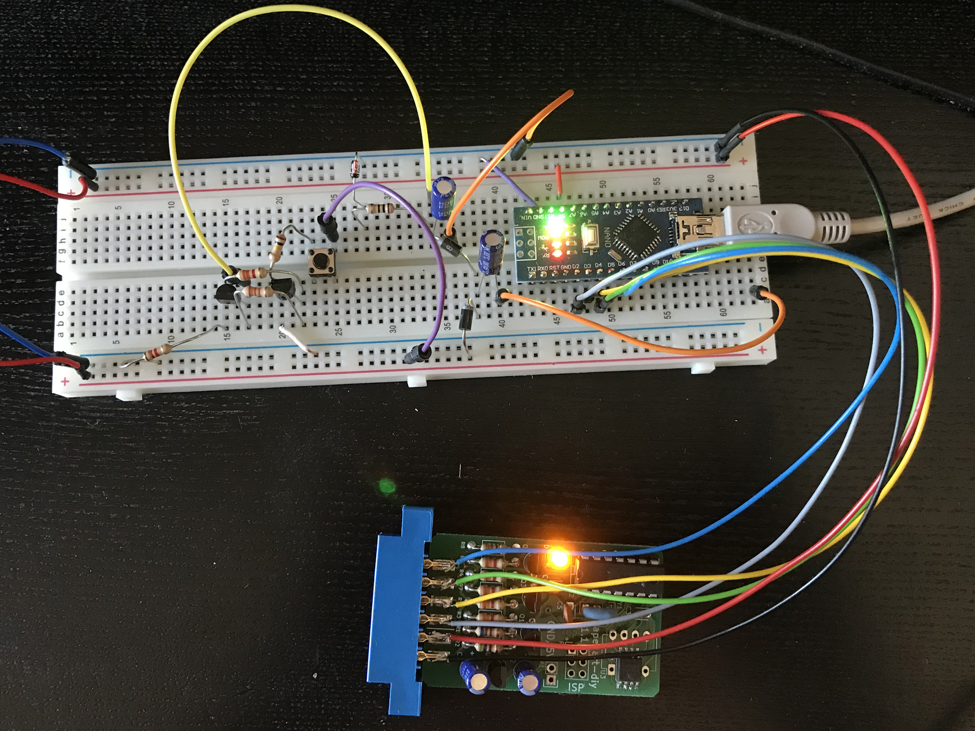
Tapecart and the Arduino. Ignore all the other components for now.
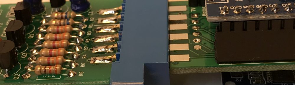
The original setup for the TapecartFlasher is as simple as it gets: simply hook up 5V and GND from the Arduino, then connect the 4 remaining lines of the cassette port interface to D2-D5. I tried this on a breadboard first and it worked out of the box! The most complicated part here was the lack of a proper connector, so I just soldered leads to the Tapecart module.
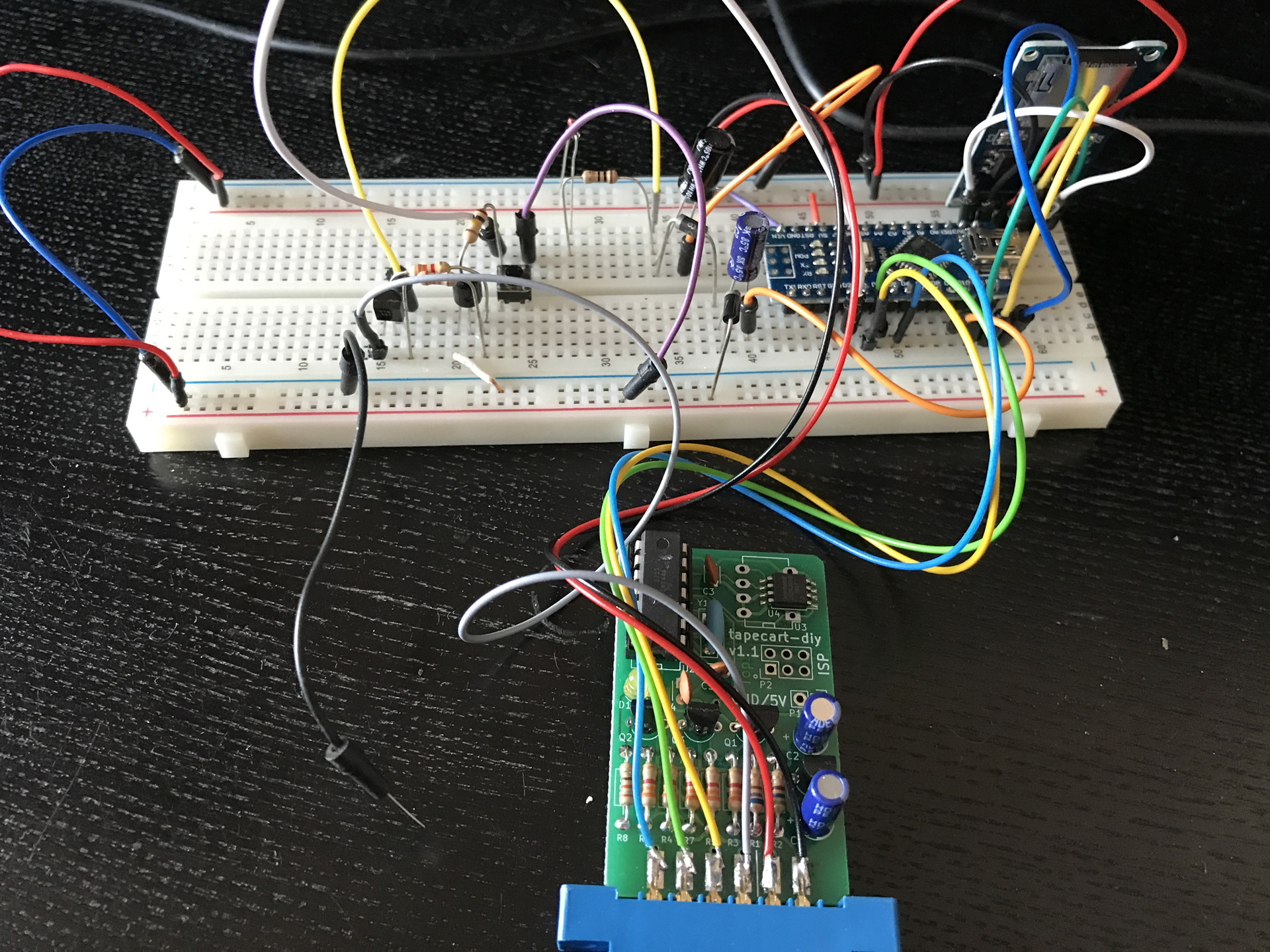
Testing the charge pump circuit.
When I read about the idea for the TapecartFlasher, I immediately wanted to create a simple adapter board for it. Besides tidying up the mess of cables, such an adapter should address another issue: the Tapecart actually expects a voltage of 7V on the the MOTOR line, because that is what the C64 provides – originally intended to drive the motor of the 1530 Datasette with 6V under load. While in practice the voltage provided by the Arduino pin seems to be just high enough to still work with the Tapecart, I would like to be sure.
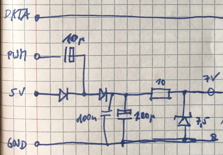
First draft of the charge pump.
As the MOTOR line doesn’t need to drive much of a load on the Tapecart, a simple charge pump circuit seemed to be the easiest and cheapest way to produce the required voltage. Using 2 diodes, 2 capacitors, and the PWM output from the Arduino, the supply voltage of 5V is (almost) doubled and then limited to 7.5V through a Zener diode.
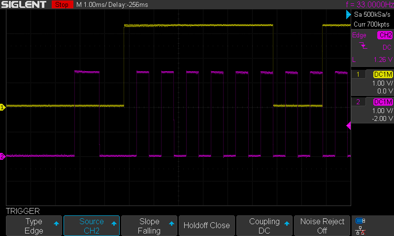
Without charge pump. Ch1: WRITE, Ch2: MOTOR
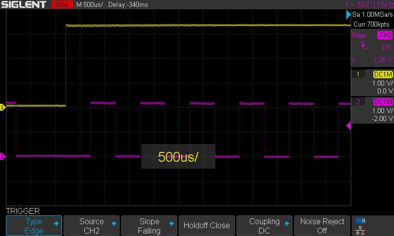
With charge pump. Ch1: WRITE, Ch2: MOTOR
The last item I added to the layout of my adapter board is a connector for a generic Micro SD module that is available on eBay for a very small price. Upcoming versions of the TapecartFlasher firmware will support up- and download of images directly from the SD card, further increasing the transfer rate.
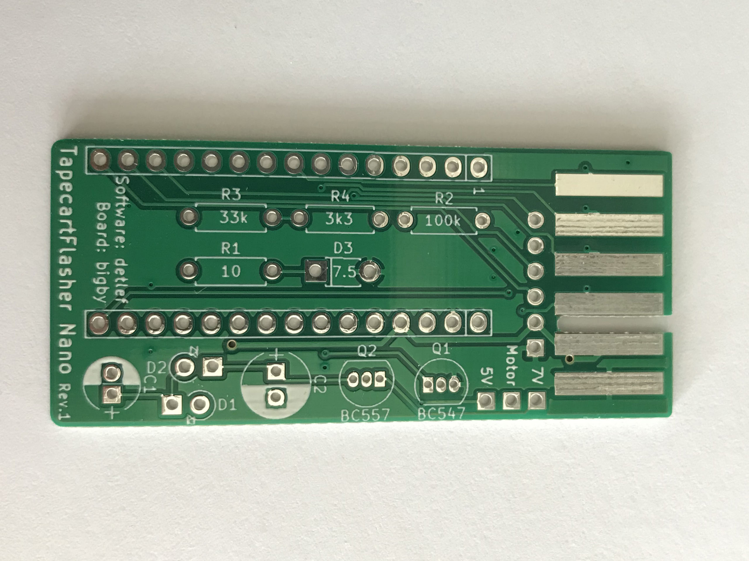 The adapter board comes as a shield for the Arduino Nano or compatible boards and is thus dubbed the “TapecartFlasher Nano”. The first prototype batch I ordered turned out fine. The board requires simple through hole components, only. This should allow anyone with some basic soldering skills to create their own adapter.
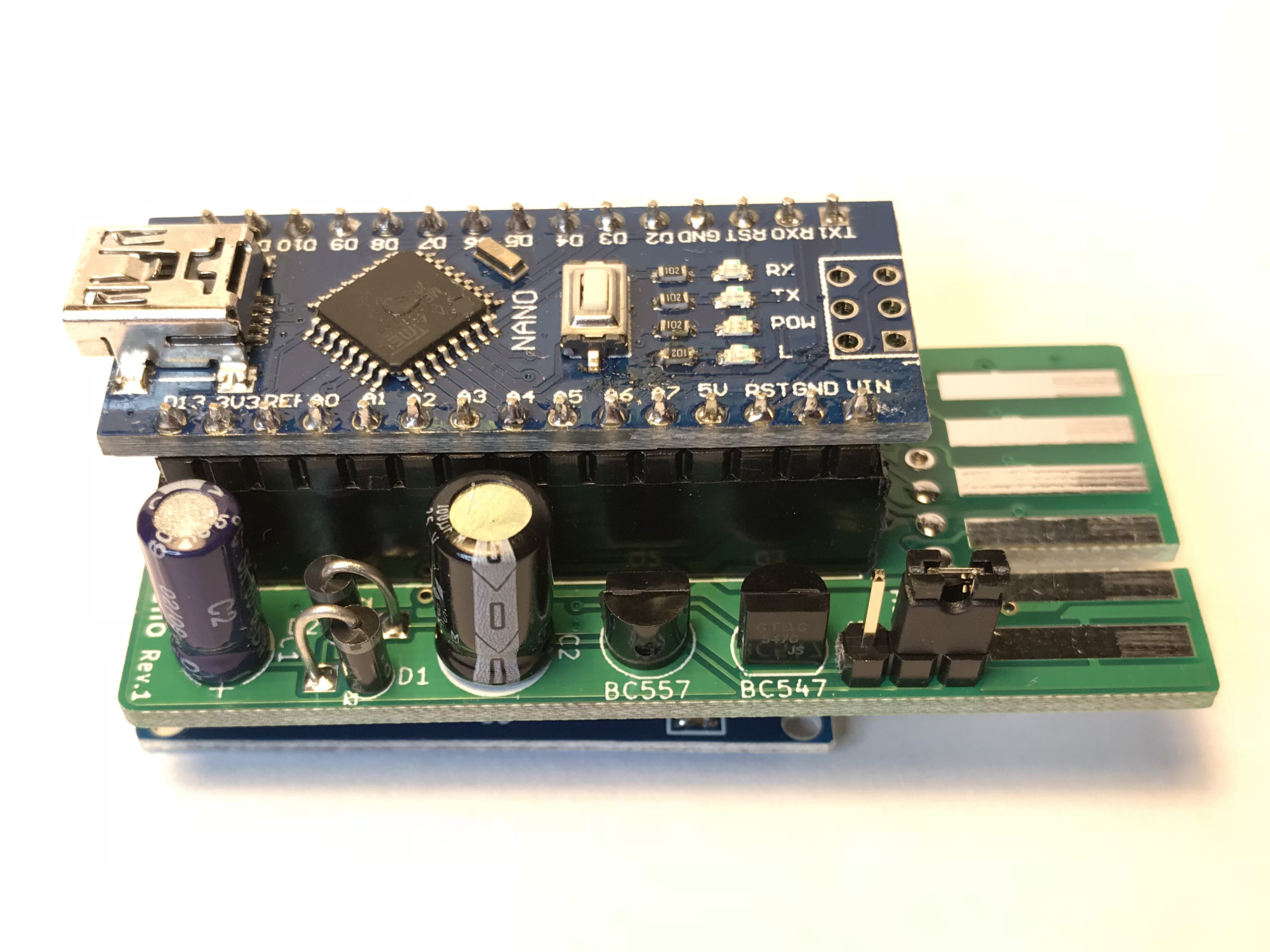
TapecartFlasher Nano assembled.
In its simples form, all that is required is an Arduino Nano that can either be soldered directly to the board or connected via two rows of 1×15 female socket strips. In this case the motor voltage must be set to 5V using jumper JP1. The other components are needed to raise the voltage of the motor signal. When those are fit to the board, the motor voltage can be set to 7V.
| 1 | C1 | e-cap 10uF | eBay (China) |
| 1 | C2 | e-cap 100uF | “ |
| 2 | D1,D2 | 1N5817 Schottky diode | eBay (China) |
| 1 | D3 | 6.8V Zener diode | eBay (Germany) |
| 1 | J2 | 1×06 female socket strip, 2.54mm, angled | eBay (China) |
| 1 | J2 | Micro SD module, SPI | eBay (China) |
| 1 | JP1 | 1×03 pin header strip, 2.54mm | eBay (China) |
| 1 | JP1 | jumper cap | eBay (China) |
| 2 | P1,P2 | 1×15 female socket strip, 2.54mm, straight | “ |
| 1 | Q1 | BC547 transistor | eBay (Germany) |
| 1 | Q2 | BC557 transistor | “ |
| 1 | R1 | resistor, 10Ω | eBay (China) |
| 1 | R2 | resistor, 100kΩ | “ |
| 1 | R3 | resistor, 33kΩ | “ |
| 1 | R4 | resistor, 3.3kΩ | “ |
| Arduino Nano (clone) | eBay (China) |
I tested the TapecartFlasher Nano with an early-access version of the firmware that I got directly from Detlef. I then modified the sketch further, adding the code to activate the PWM output on D9 that is needed for the charge pump.
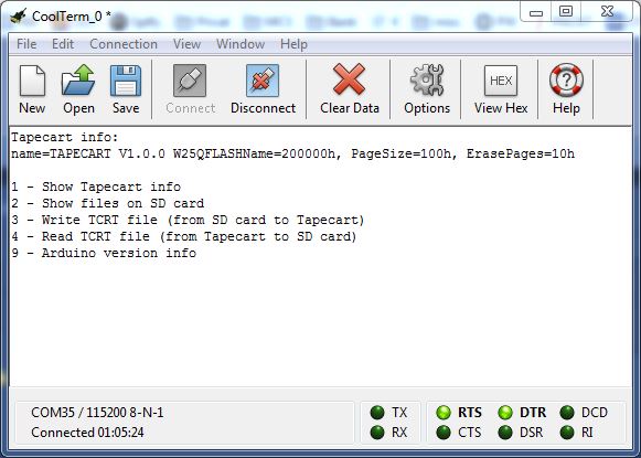
Early version of the console interface.
Data upload from the PC to the Tapecart is controlled through a small GUI for Windows. A newly integrated console interface allows the data transfer between the Tapecart and the SD card. With my ATtiny44 based Tapecart – which is quite slow in calculating the CRC checksums – I measured somewhere between 4:10 and 6:50 minutes for a complete TCRT upload, depending on the setup. Quite some improvement!
Both the code for the updated firmware and the project files for the adapter board will be available once we are done testing. Also, PCBs for the SMD version of the Tapecart are on their way from China. So there will be more on the Tapecart topic, soon. Stay tuned!
Update 1: On closer inspection, the voltage on the motor line seems to be a tiny bit too high. A 6.8V Zener diode should be used instead of the 7.5V one.
Update 2: The project files for rev.1 and rev.2 of the TapecartFlasher board are now available on Github.


Pingback: The 32-Bit Tapecart | hackup.net
Pingback: News Bits: Awards, Revisions, and Cases | hackup.net
Do you know if someone produce and sell those adapters? Thank you
I now that poly.play was preparing to produce and sell fully assembled Tapecart Flashers but I can’t find them there, yet. It might be worth contacting them. Myself, I’ve got a few kits left over that I have offered on Forum64. But international shipping is no longer cheap from Germany as of this year, I’m afraid. If you are still interested in one of those kits feel free to drop me an email.
Hello there. Thanks for your articles. Would you know if there is any PC software to create the TCRT image ?
The only software which runs on a PC to create TCRT images that I know of is the “Tapecart Browser”. I’ve linked to it in my post on the Tapecart itself. It is a PHP script to be used on the command line, though.