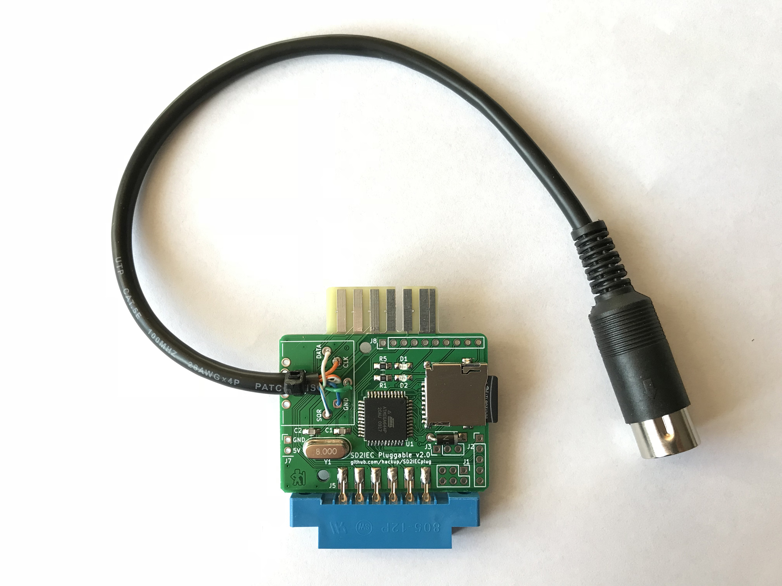
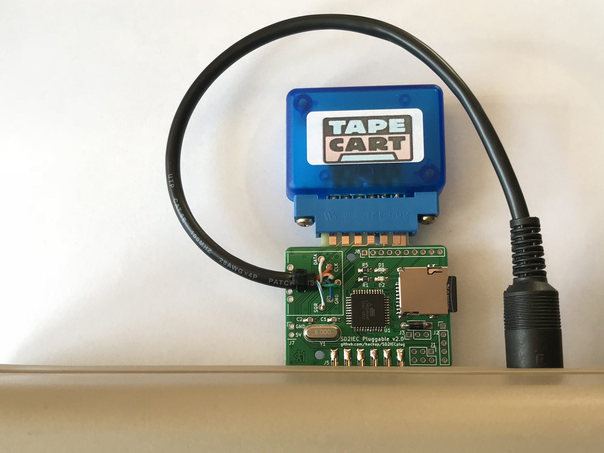
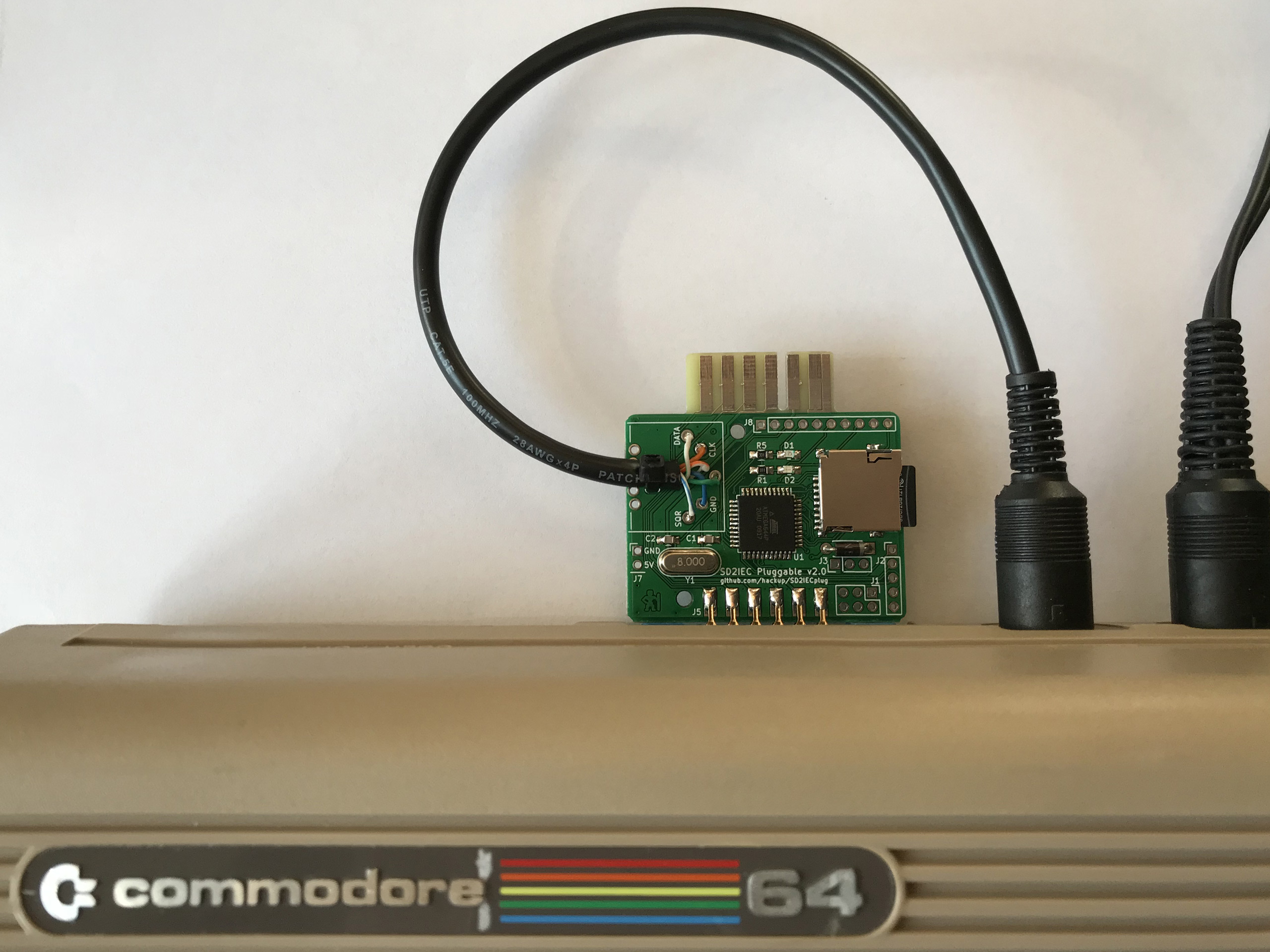
Last year I created my own rendition of the SD2IEC, dubbed the SD2IEC Pluggable. Version 1.0 left some room for improvement and recently I found the time to take on a new revision. The new version 2.0 is even closer related to the design published by Shadowolf while maintaining the “pluggable” layout with the pass-through tape connector.

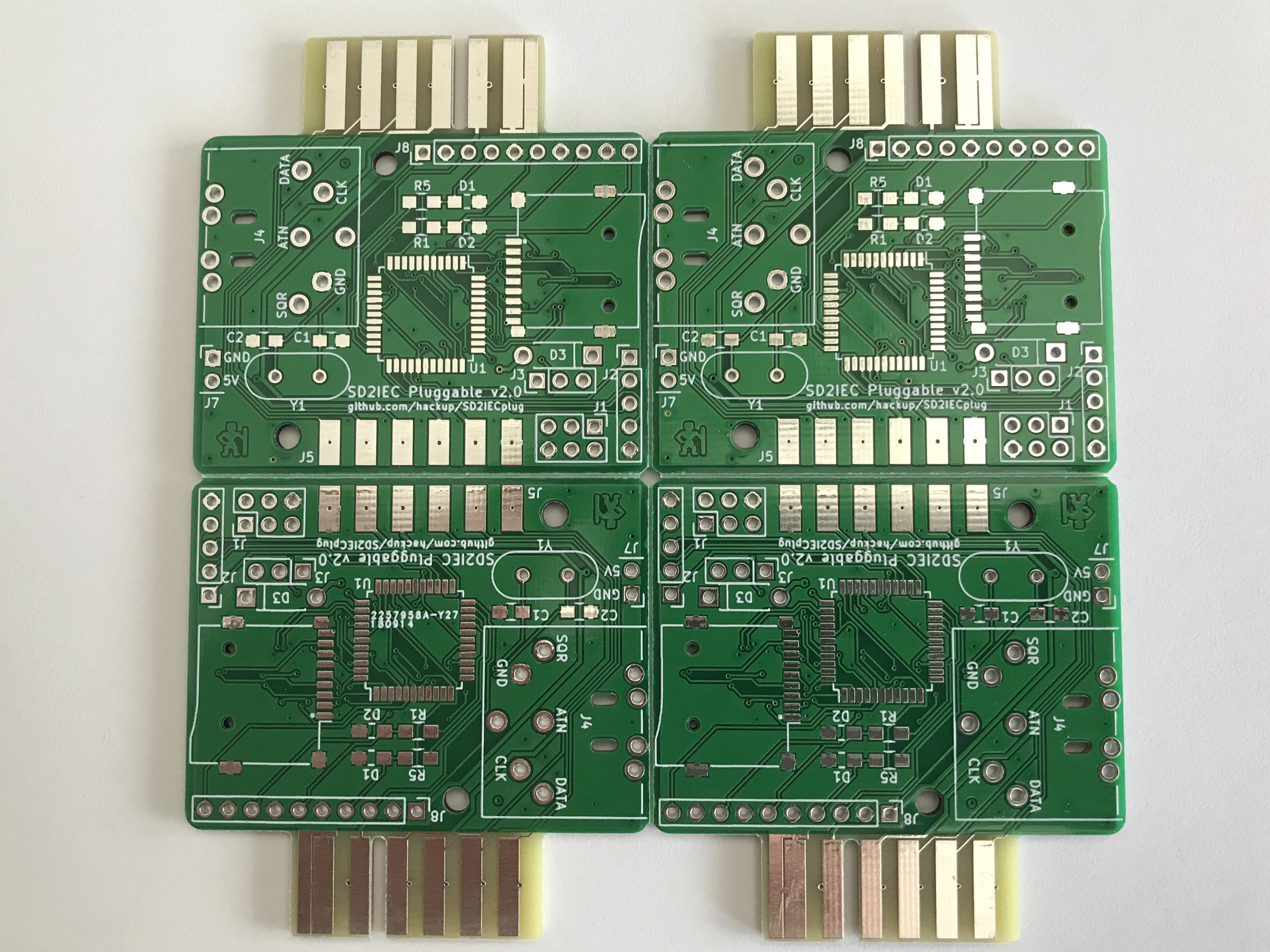
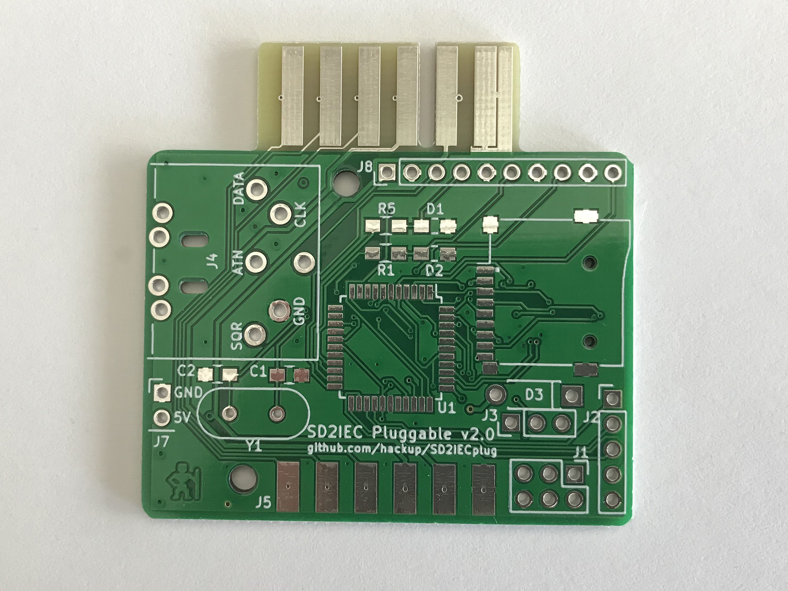
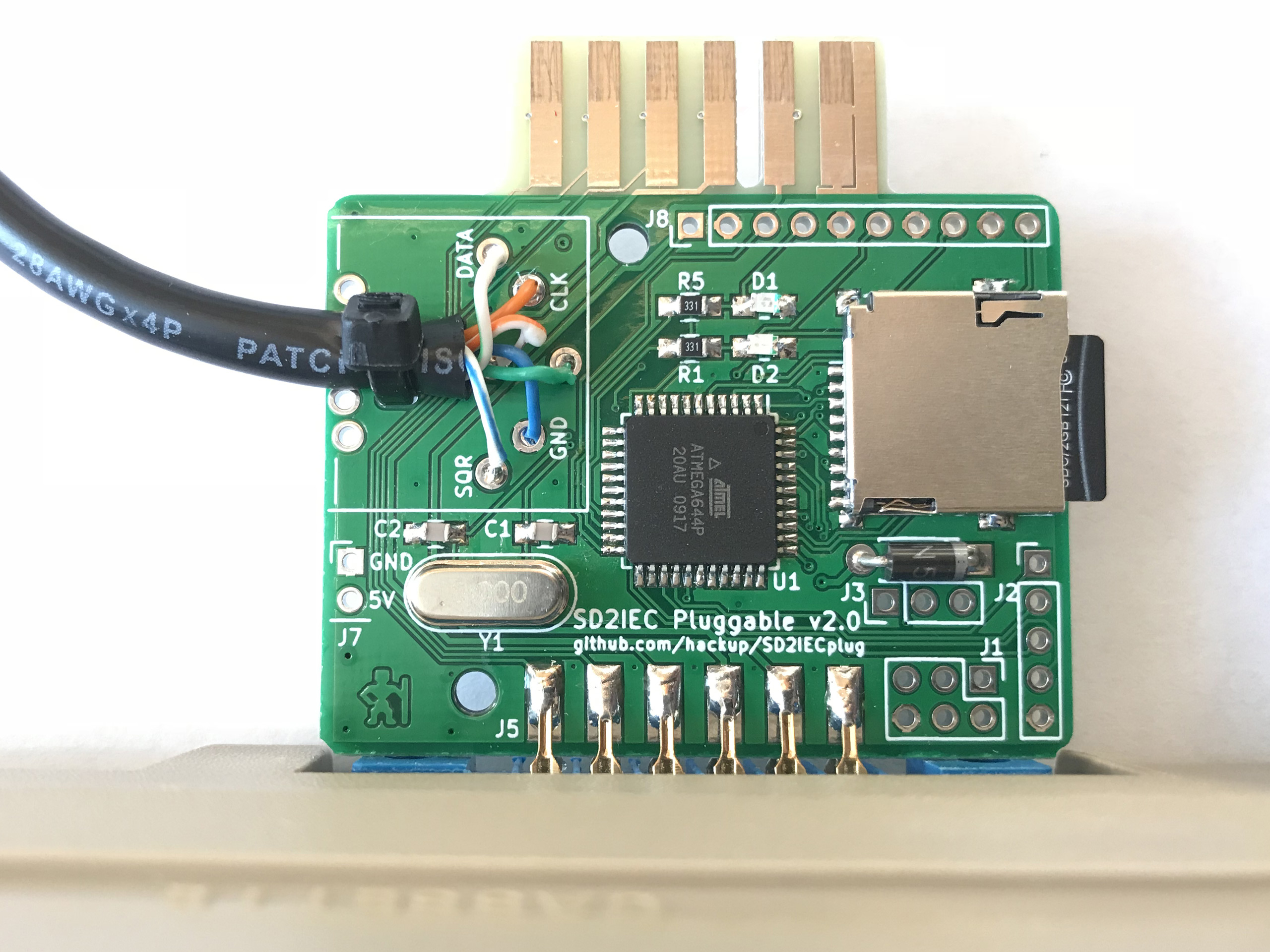
Most notably, the size of the PCB has been reduced by more than 50%. To achieve this, the SD slot has been replaced by the micro variant and the external USB power supply option was ditched. The components for the intended Tapuino integration — which never came to be — are gone, too.
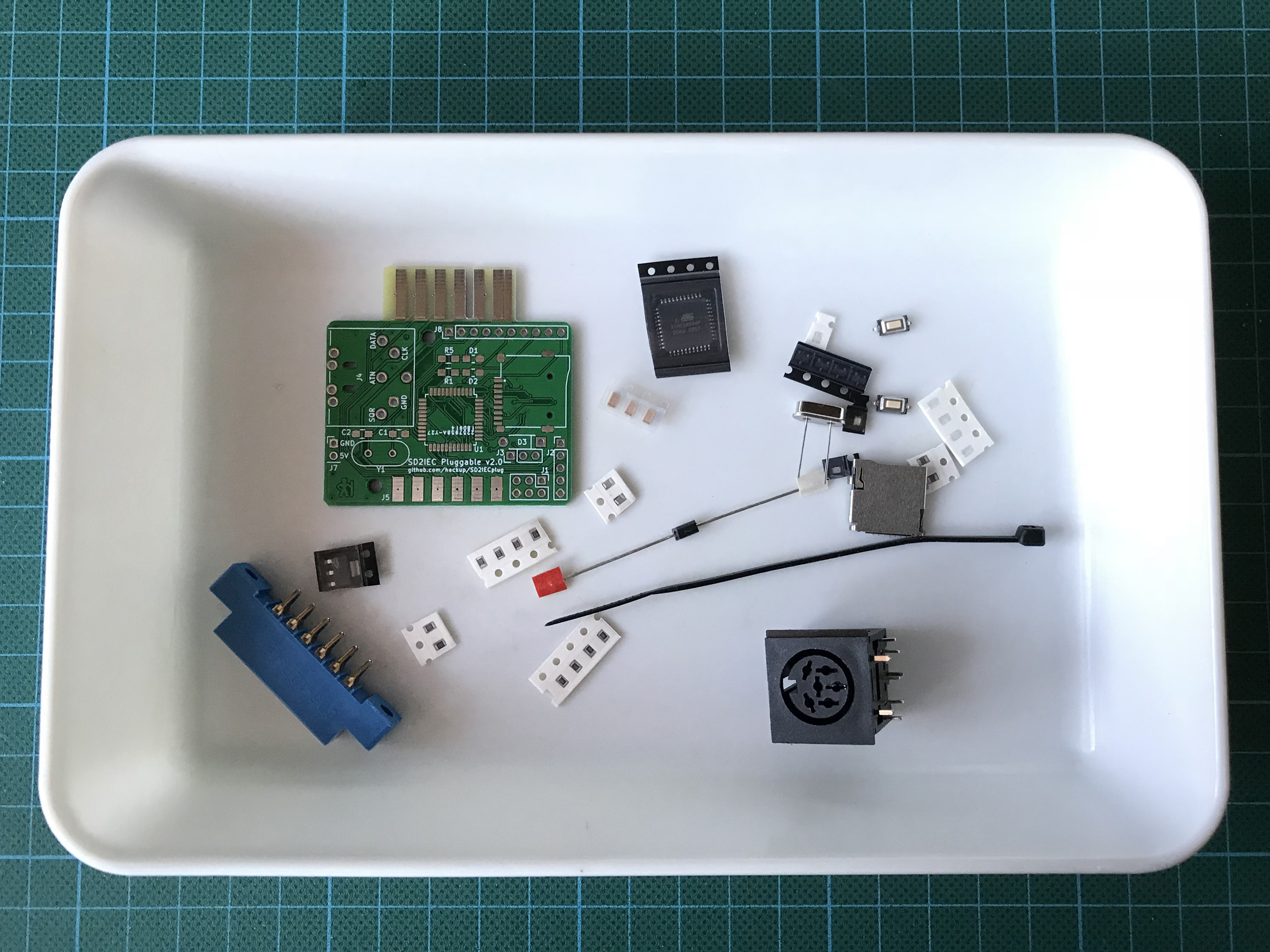
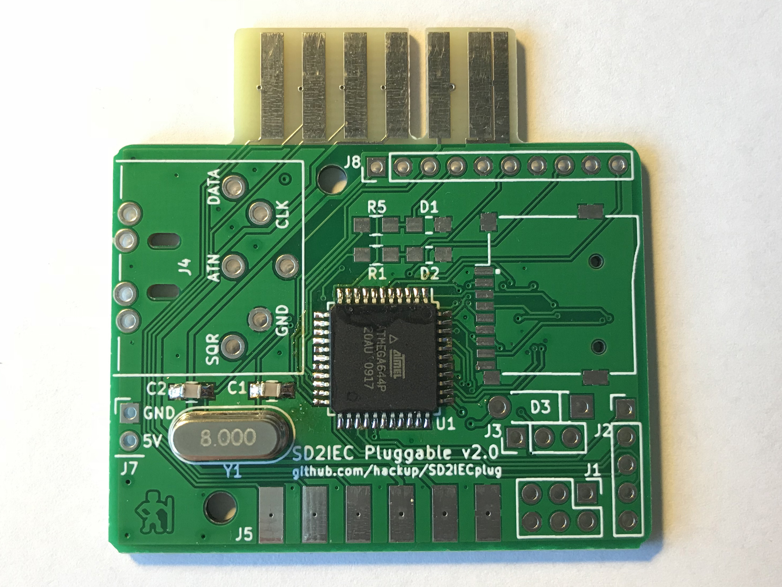
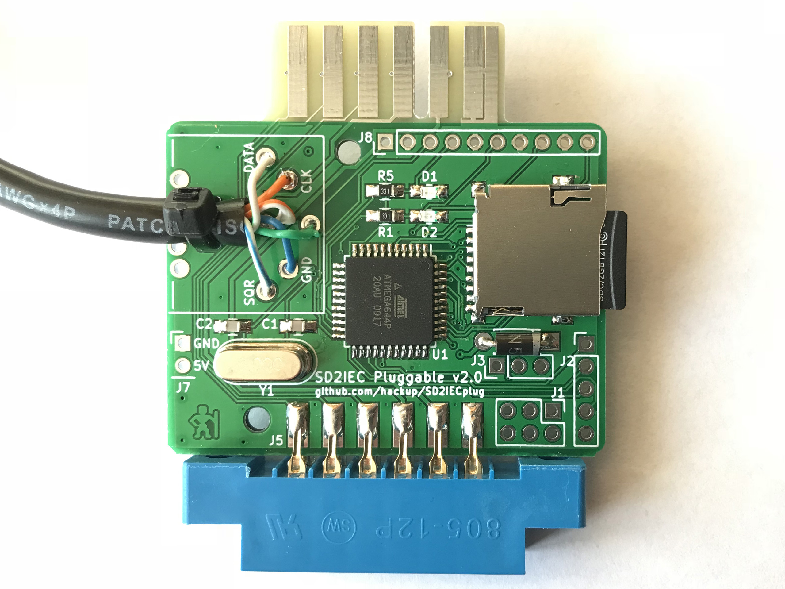
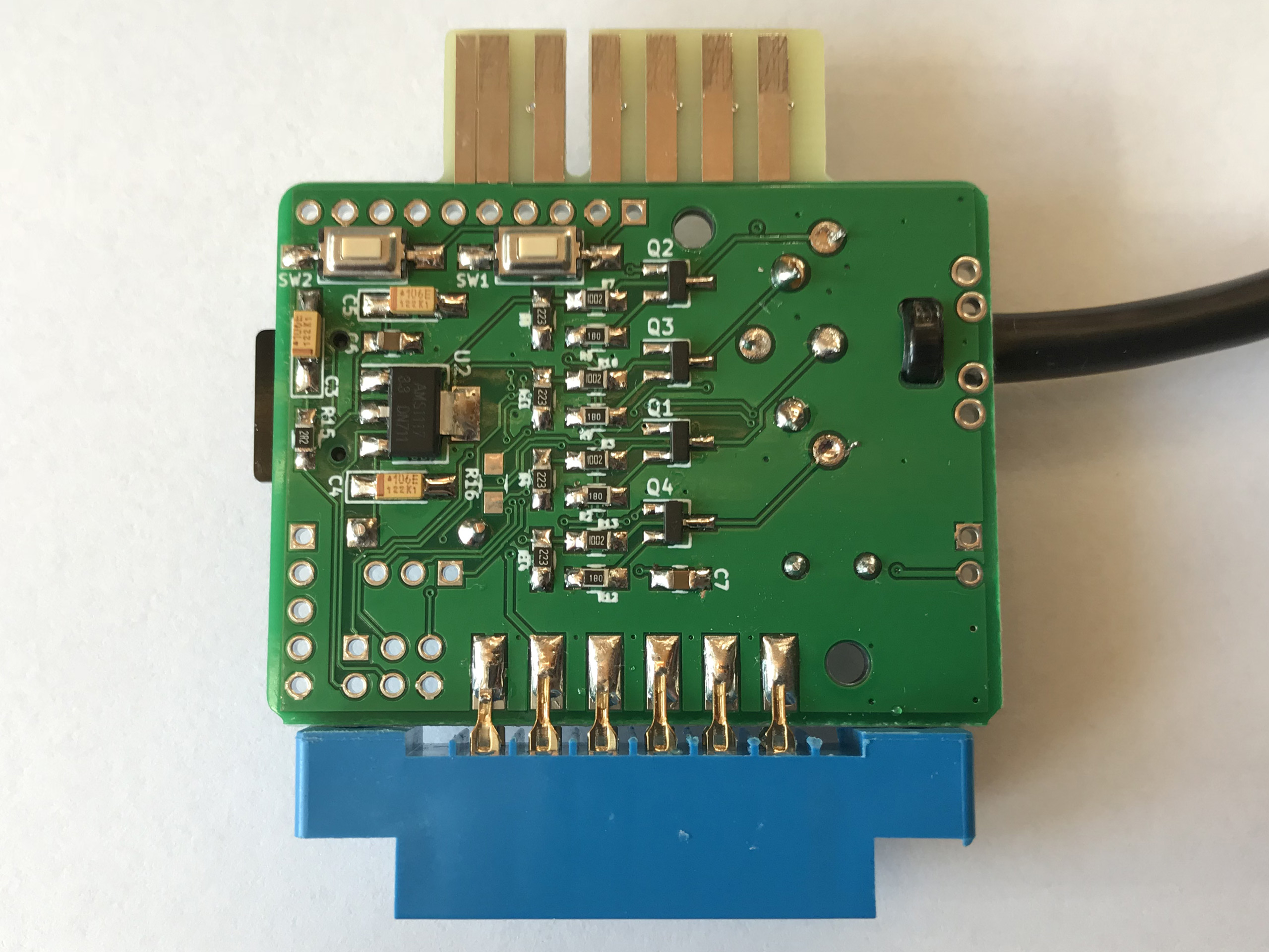
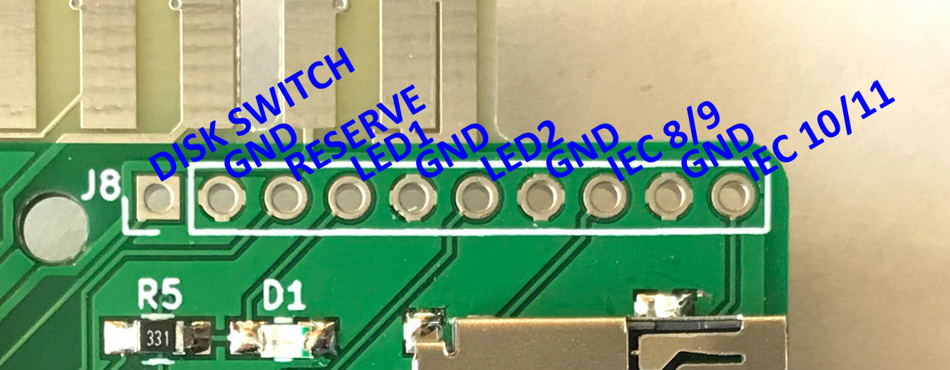 Instead, there are new breakout connectors that were previously missing, giving access to pins for connecting external LEDs, disk switch buttons, an LCD daughter board, and device id selection. Here is the bill of materials:
| 1 | XS1 | Micro SD Slot | eBay |
| 1 | J4 | 6 pin DIN socket | eBay |
| 2 | C1-2 | 56pF capacitor 0805 | eBay (China) eBay (Germany) |
| 3 | C3-5 | 10µF tantalum capacitor 3216 | eBay |
| 2 | C6-7 | 100nF capacitor 0805 | eBay |
| 1 | D1 | LED 0805 red | eBay |
| 1 | D2 | LED 0805 green | “ |
| 1 | D3 | 1N5817 | eBay |
| 4 | Q1-4 | BSS138 FET | eBay |
| 2 | R1,R5 | 0805 resistor 330Ω | |
| 4 | R2,R6,R9,R12 | 0805 resistor 18Ω | |
| 4 | R3,R7,R10,R13 | 0805 resistor 10kΩ | |
| 4 | R4,R8,R11,R14 | 0805 resistor 22kΩ | |
| 1 | R15 | 0805 resistor 2.2Ω | |
| 2 | SW1, SW2 | SMD push button 3x6mm | eBay |
| 1 | U1 | ATMega644-20AU or ATMega1284 | eBay eBay |
| 1 | U2 | AMS1117-3.3 voltage regulator | eBay |
| 1 | Y1 | HC49 crystal 8MHz | eBay |
Once the new version has been sufficiently tested and if everything seems to work, the project files will again be freely available.
Update 1: While it is generally working fine, there are a few minor issues in version 2.0 that I will address:
- The numbering of LED 1 and 2 has accidentally been swapped.
- There should be some more space between the data lines and the zip tie drill holes to give some leeway for less-than-accurate manufacturing.
- Speaking of zip tie holes: they could be a little bigger.
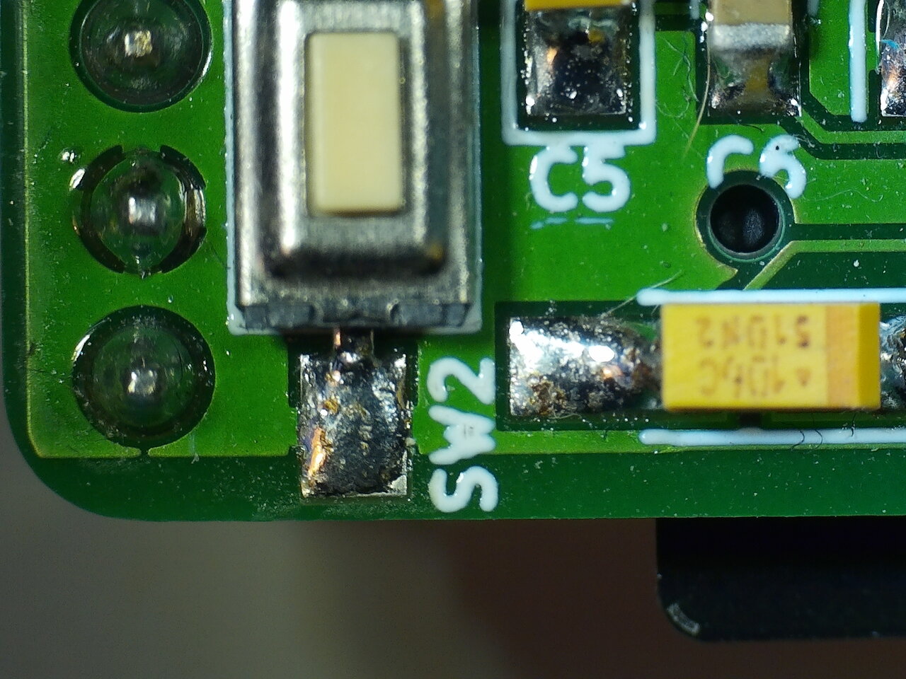
- The ground plane and the solder mask layer around the edge connection fingers could be placed better.
Update 2: Finally, after enough people kept nagging me, I managed to clean up the repository. So, the KiCAD project files are again available on Github in case you’d like to make your own pluggable SD2IEC. If you do, I would love to hear about it in the comments!
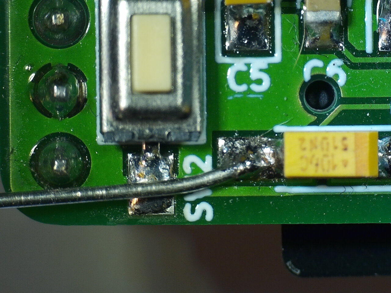
Update 3: In the meantime, an embarrassing though seemingly not very dire bug in the schematics of version 2.0 has been brought to my attention.
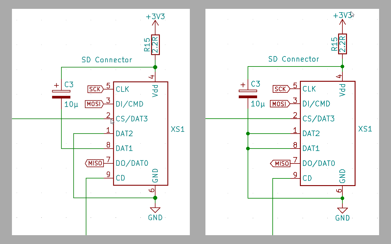
The flawed v2.0 schematic on the left, the corrected v2.2 to the right.
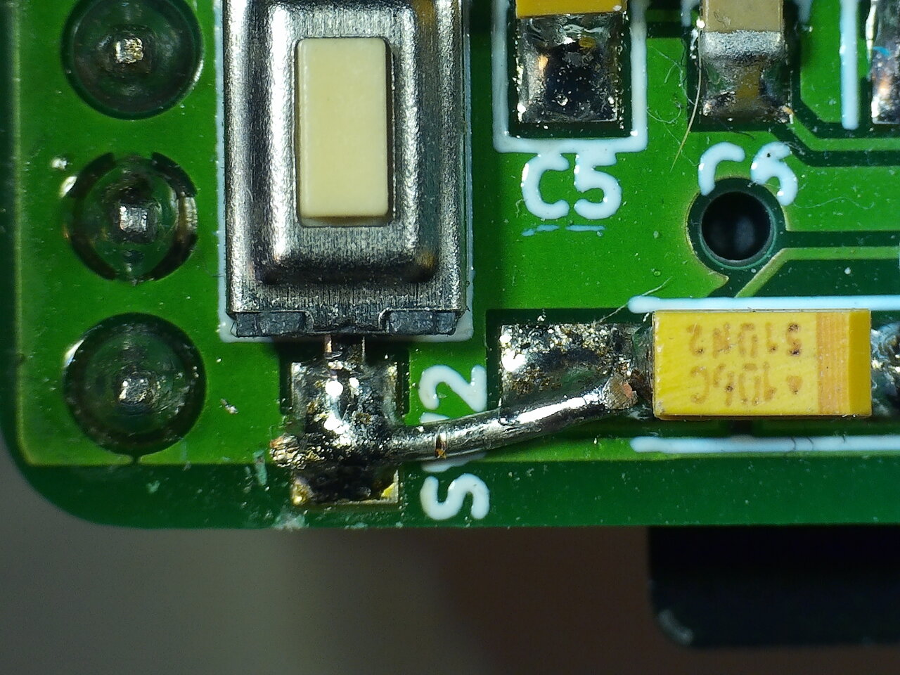
This has already been corrected in version 2.2, but if you are using a v2.0 board you can easily fix it using a small jumper wire on the bottom side of the PCB.

Jumper wire fixing v2.0 of the PCB.
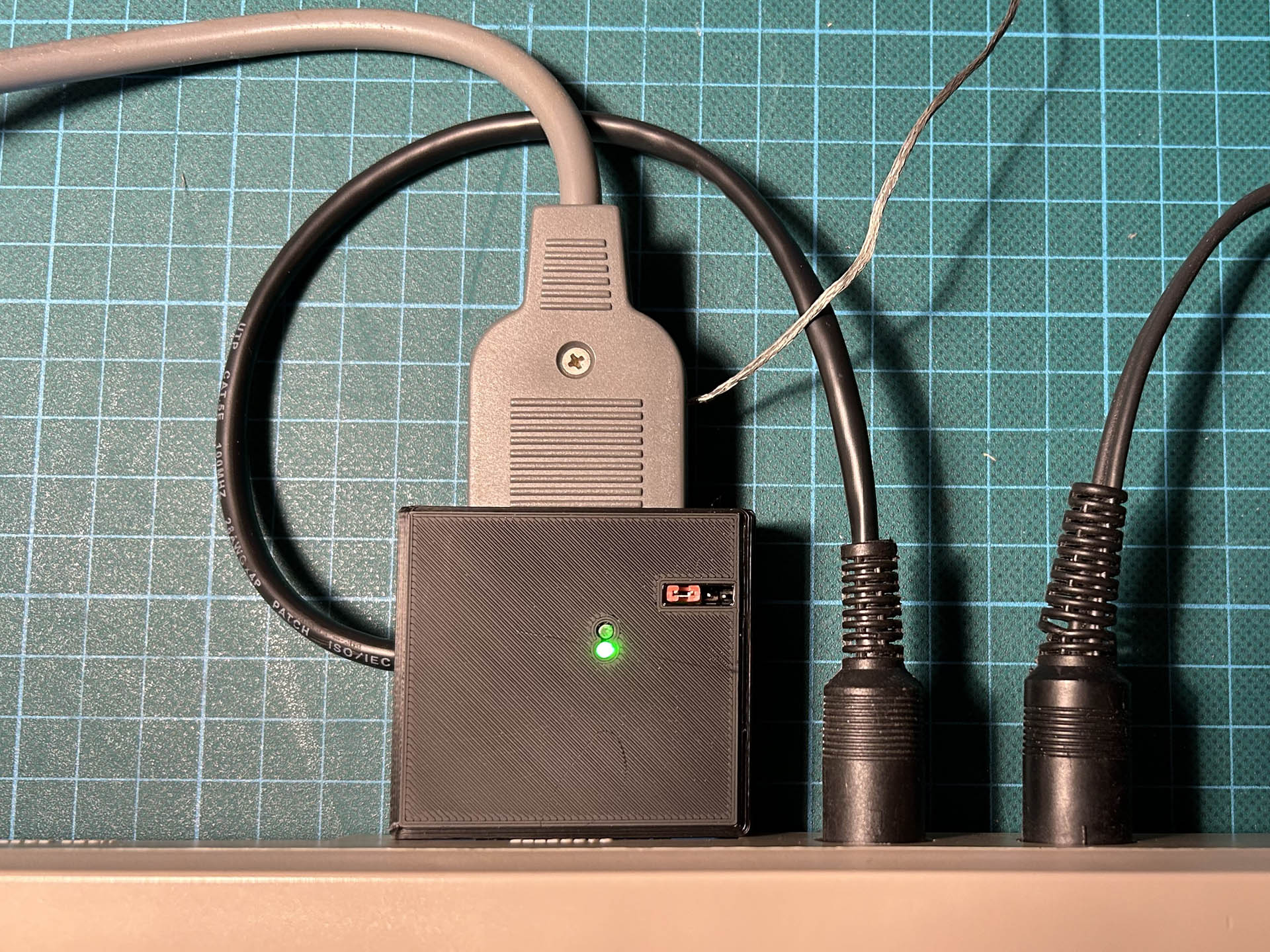
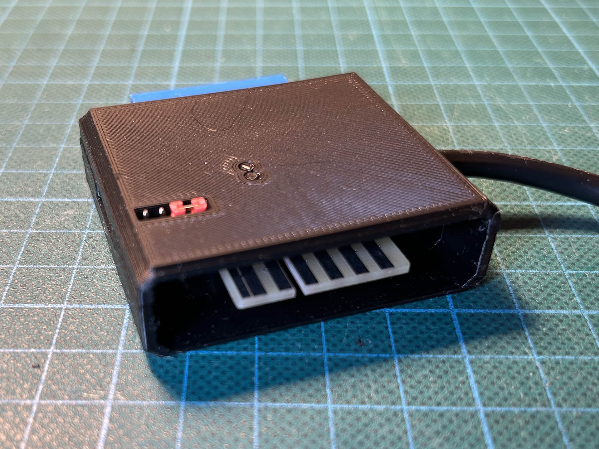
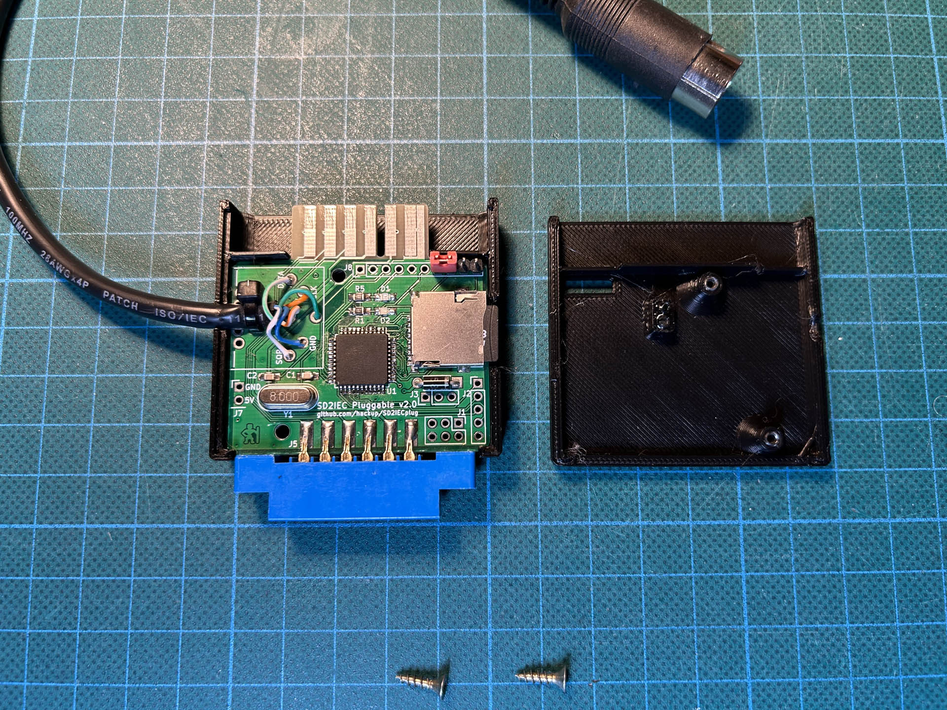
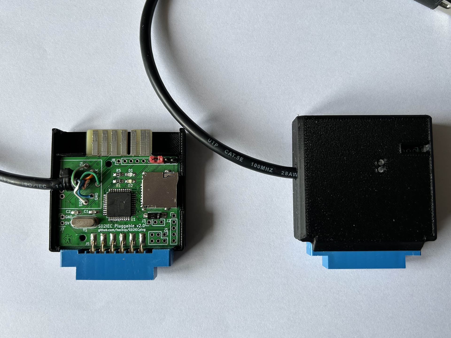
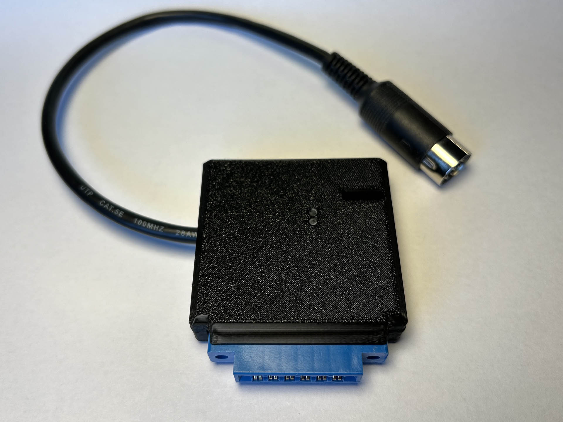
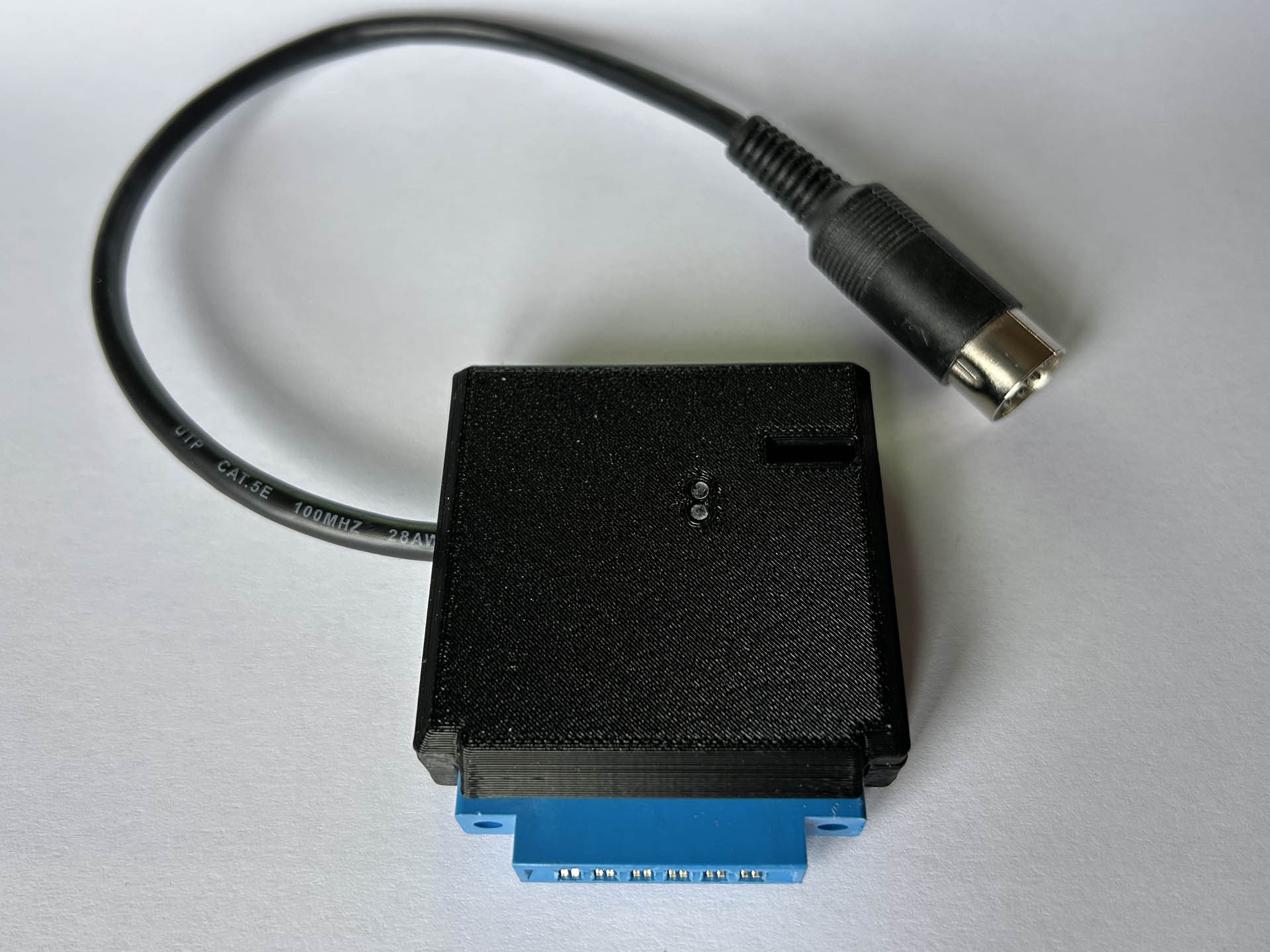
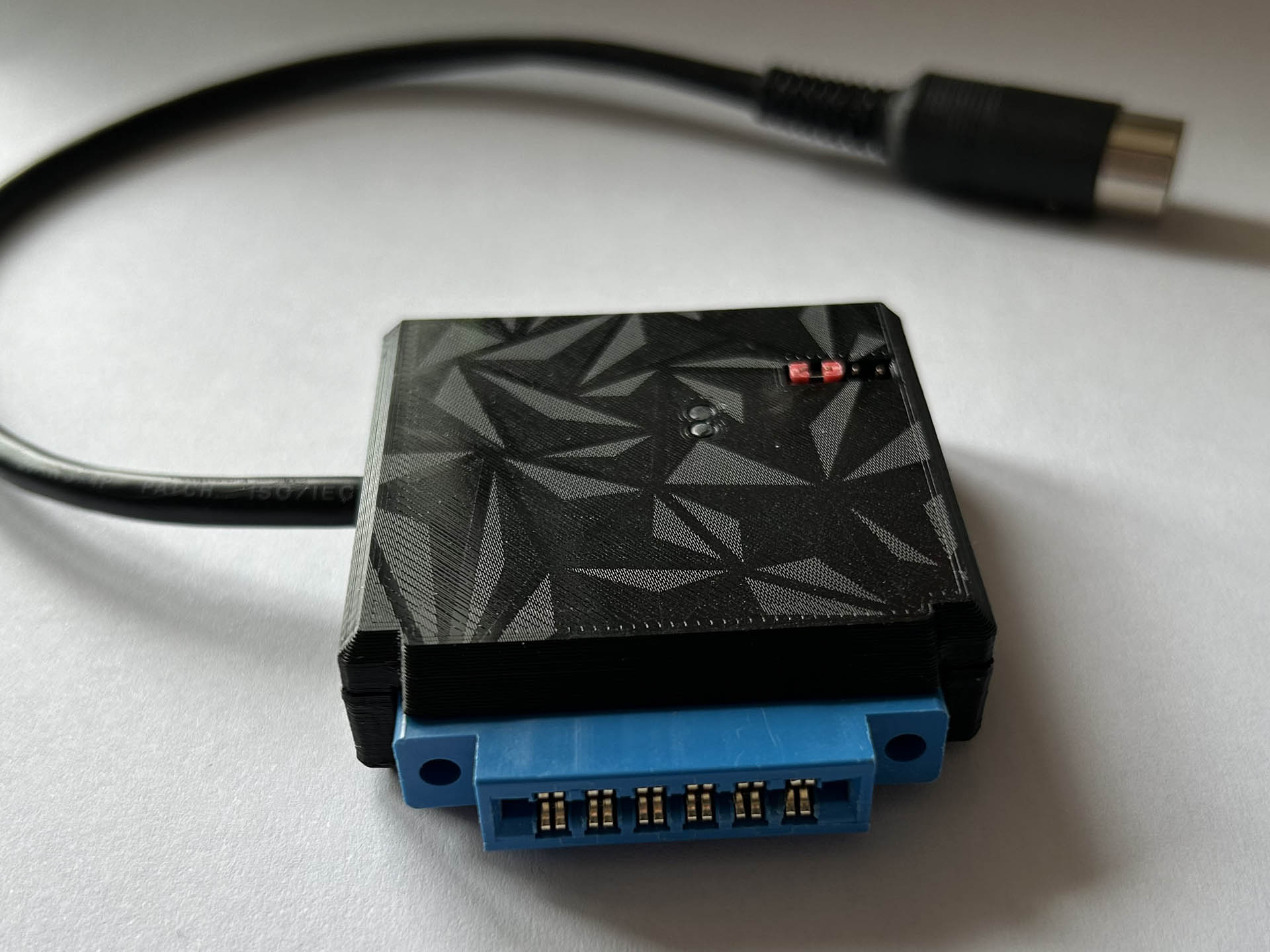
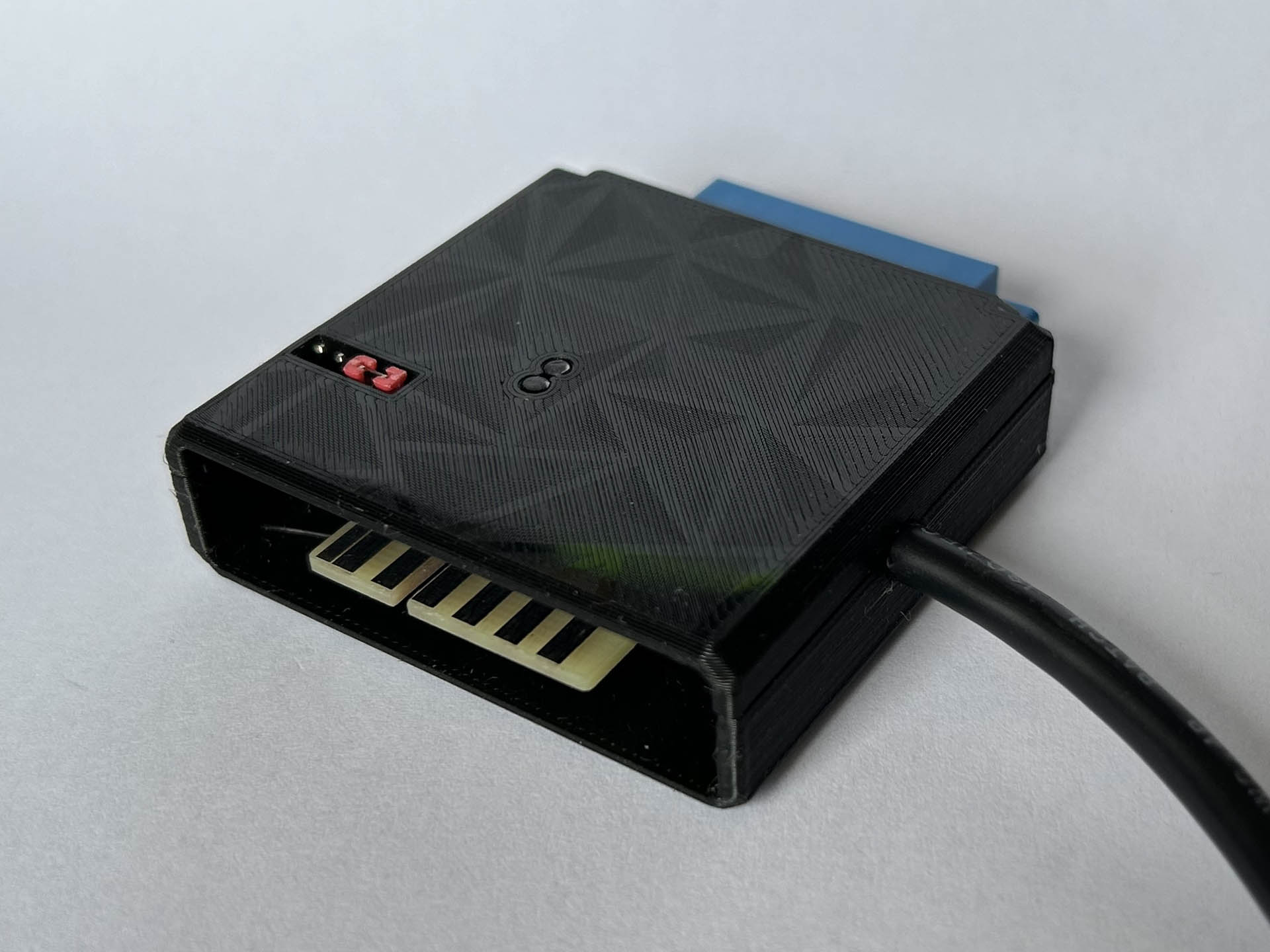
Update 4: I finally created an published a case for this project. Currently, it will fit only version 2.0 of the SD2IECplug. The STL files for 3D printing are available for personal use on Thingiverse and Printables.

The SD2IECplug in a 3D printed case.
Nice Job!
If you plan any redesing, for practical use I would move the IEC Port to the other side. Since the IEC Port of the Commodore 64 is on that side too.
Thanks, Robert! I considered moving the IEC port. But if I moved it to the other side and then actually fitted the DIN socket, the plugs on both ends of the IEC cable would block each other, I think.
This is a common mistake regarding pin marked as “reserve”, as in original schematic. It is a typing mistake, because correct name should be “reverse”, in opposite at “disk switch” button, that someone named also “forward”.
So, these 2 pins, “forward” (aka diskswitch) and “reverse” (aka reserve) change disk “seen” by sd2iec according to “autoswap.lst” in direct or reverse order.
Best regards, Enzo.
Hi, any updates on your great work on this one? I’m very interested to build my own 🙂
Hi Pat, you are right, it seems like I never got around to cleaning up my latest changes and pushing them to Github. I still need to update the README and such. Maybe I’ll find the time to do that next week.
Hi,do you have a pcb for sale?
Hi there!
nice project, I want to biult it at myself. Can you tell me where can I find hex for Atmega 644?
You’ll find all current binaries to flash the MCU on sd2iec.de.
Thanks, but I don’t see there HEX for Atmega 644 (I have Atmega 644 20AU). Which hex dump select? Do You know cprrect fusebits for it?
No, but there is the correct BIN file in that archive. What do you need the HEX file for? The files with “SW2” in their names are those for the Shadowolf variant. These are the fuse settings to use, if I recall correctly: L=0xEF H=0x92 E=0xFD
Hello,
I have this sd2iec, give are Reset Pin? Have no found on this pcb
Thanks
I’m not sure exactly which reset pin you are looking for and what you intend to do with it. If you mean the reset pin of the ATmega, that pin is connected to the ISP header and could easily be accessed there.