The two 9-pin Control Ports located on the right-hand side of the C64 are used to connect joysticks and other input devices like paddles or even a mouse to the 8-bit computer.
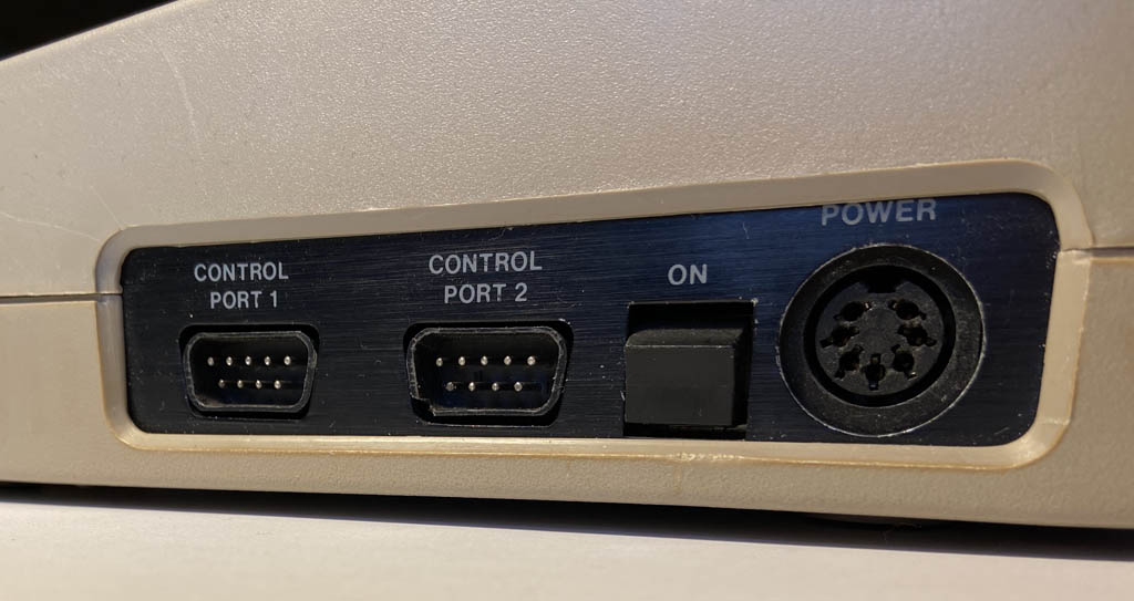
The two Control Ports.
The digital input pins are directly connected to one of the two 6526 Complex Interface Adapters (CIA) inside the C64, without any protection on the motherboard.
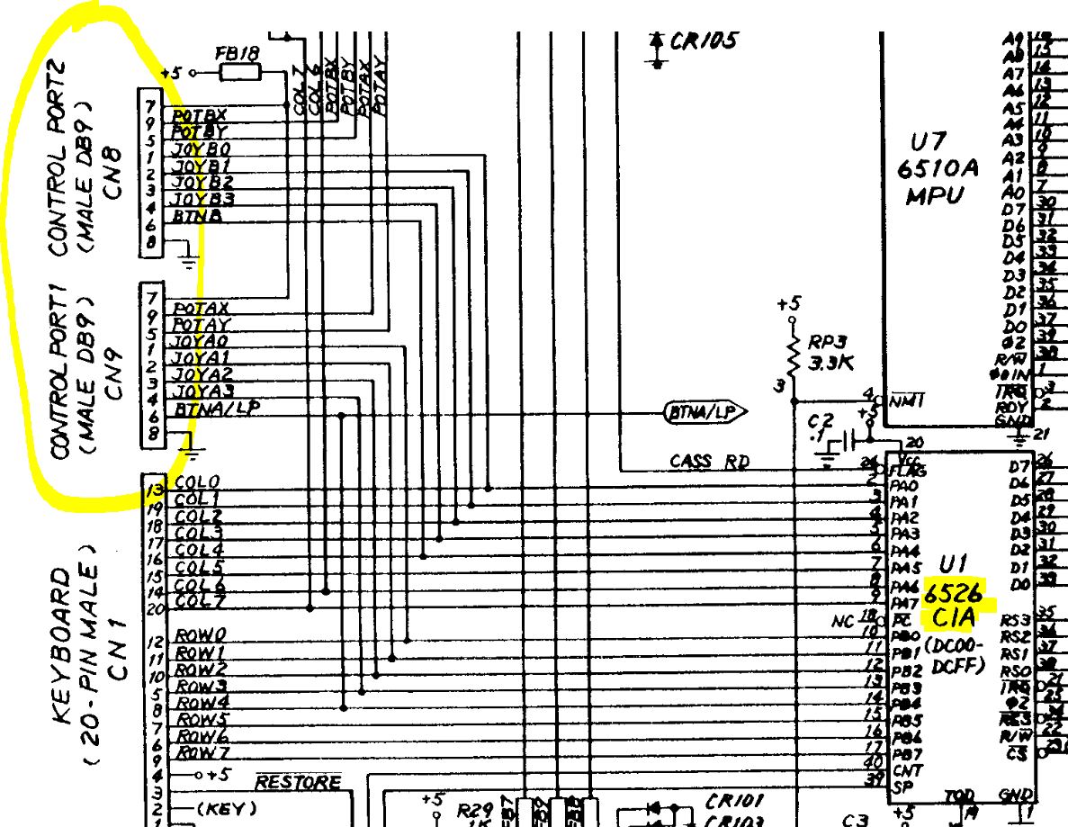
Direct connection to the CIA.
These old I/O controller chips are more sensitive than comparable modern counterparts and are easily destroyed by electrostatic discharge (ESD) that can occur, e.g. when touching the 9 connector pins with a finger.
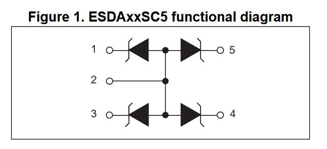
The ESDA5V3SC5 Zener diode array.
One way to protect an input pin against ESD is by using a suitable Zener diode to direct such an overvoltage towards ground. Today, arrays of such diodes are available for exactly this purpose like the the ESDA5V3SC5 made by STM which comes in a tiny SOT23-5L package and contains four Zener diodes with a breakdown voltage of 5.3V.
This protection method is actually very simple. The hardest part is to wire the diodes to the motherboard of the Commodore in an easy, reliable, and unobtrusive way. Others have come up with solutions for this problem in the form of tiny PCBs that hold the diodes and are soldered to the underside of the motherboard, over the 9 pins of the Control Port connectors. I first came across this idea in a thread on Forum64, which again references (or rather: mentions) earlier works by others that I’m having trouble finding right now.

PCB layout in KiCAD.
True to the motto “if in doubt, DIY”, I started up KiCAD and created my own version of such a protection board. I opted for a fairly large drill diameter of 1.9mm for the nine through-hole pads and a thin board of 0.6mm in order to make installing it as easy as possible. And I created a paneled PCB for manufacturing, because not doing so wouldn’t make sense considering the dimensions of a single module.
Finding a manufacturer who would produce and ship that panel at a reasonable price, with v-scoring on such a thin board and together with a solder paste stencil, turned out harder than expected. But when the package arrived, the end result was very satisfying!
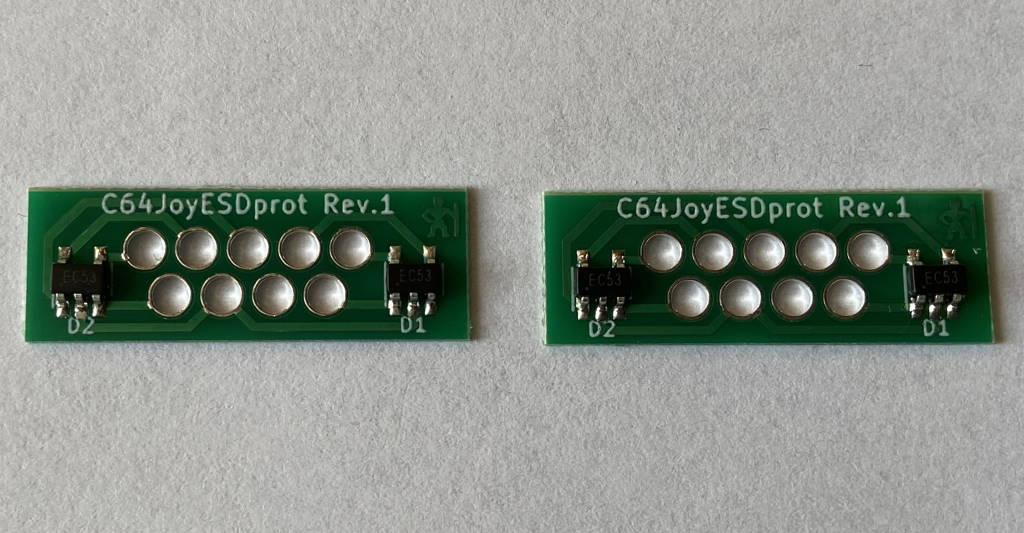
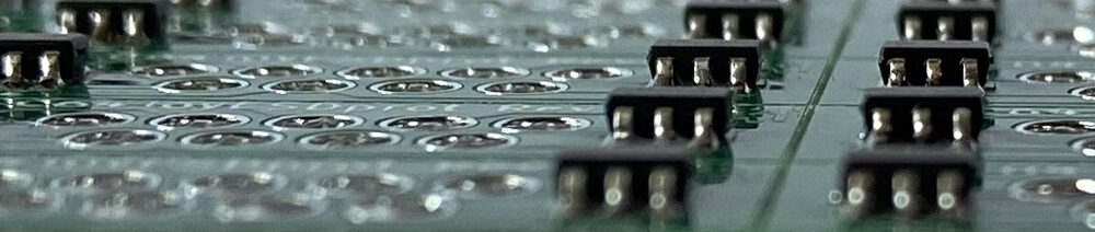
Two of the protection modules assembled.
By now, I have assembled a few of the protection boards and equipped two of my Commodore machines with them. So far, I haven’t found anything in the first revision that would need improving. Installing the modules requires only modest soldering skills:
- Turn the motherboard upside-down and “throw” the module over the 9 pins of the connector with the diodes facing away from the motherboard.
- Add a little fresh solder to one of the pins. (Start with the GND pin if you are truly paranoid.)
- If needed, heat the same solder joint again and align the module using tweezers.
- Solder the remaining 8 pins. Make sure that each pin is properly connected to its surrounding pad on the module.
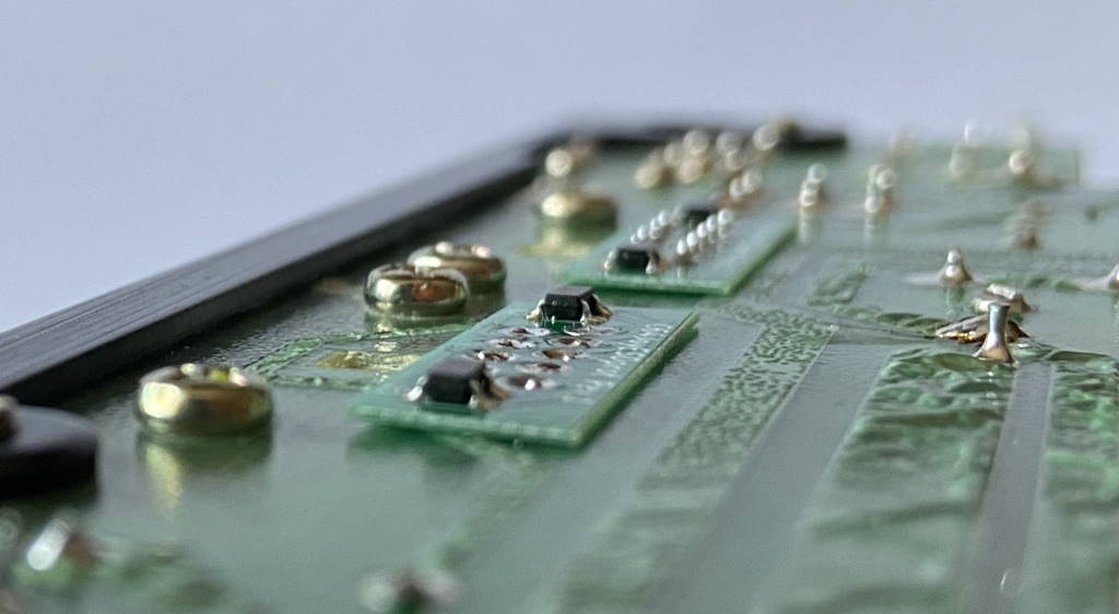
Two of the ESD protection modules installed.
As usual, my project files will be available for you to use once I’ve finished some more testing and cleaned up the repo a little.


Do you by any chance sell these?
Currently, no. Right now, we are still doing some beta-testing with a few guys on Forum64. If all goes well, I might organize a group-buy for people registered on that site.
Hi, do you have the eagle, kicad or gerber files? I’m interested in protect my C64, C128 and maybe others like msx
Hello!
I am the guy from the Forum 64. 😉
I have Gerber files for “my” PCB, nearly identical with the ones from cg.
Here ist the link:
https://www.forum64.de/wcf/index.php?attachment/162378-gerber-zip/
I used the TESD5V0L1UC and I´m too lazy to compare these two diodes now. 😉
Until now my C64 is still alive. Maybe pure luck, maybe the ESD-protection?
Who knows….. 😉
Hello,
a very interesting project. Any news?
best regards
Any news for this project?
Best regards
Were the gerbers ever released for this? I tried downloading the other ones as mentioned by Retro-Renter but I couldn’t open it with anything, and online viewers didn’t seem to work either.
Not yet, sorry.