The ZX81+38 is a clone of the Sinclair ZX81 home computer that replaces the ULA found in the original with standard logic ICs. That means, it can be built with all parts still readily available today. It was created by Mahjongg, introduced on a forum dedicated to Sinclair computers, and document on the web with construction files available on Github.
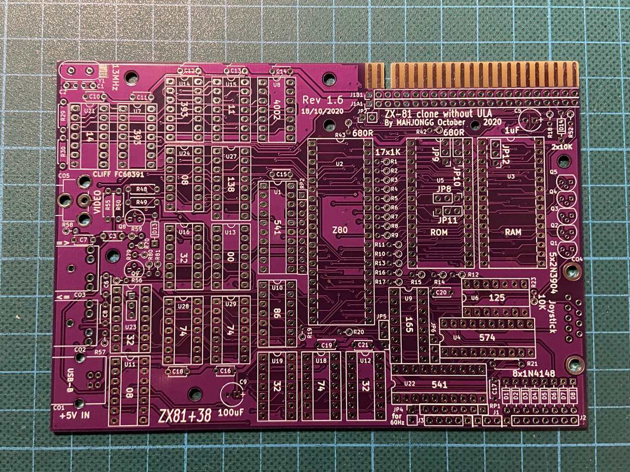
The empty PCB as I received it.
I learned of this project a while ago, when I received the PCB as a gift from a friend who had ordered more than he needed. So, even though I never owned or even used a ZX81 to that day, I wasn’t left with much of a choice and had to build one myself. After all, one cannot just not assemble such a nice PCB!
As it turned out, I had most of the required components in stock already and had to source only a few additional ones like the resistor networks or a couple of logic ICs. And of course, the RCA- and audio connectors: no matter how many of those I keep around, the next project will always require a different footprint.
Found help on Forum64 getting the correct dimensions.
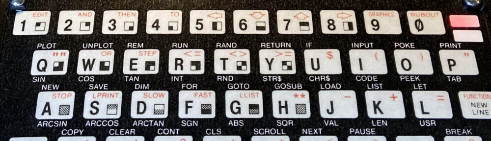
While I waited for those components to arrive, I passed my time thinking about what kind of keyboard I wanted to connect to the board when it would be finished. I know that replacements for the original membrane keyboards are still available from the UK and I wouldn’t hesitate to get one of those for an original ZX81. But for this project, I felt that something DIY would be more appropriate. Also, I would have needed to find matching sockets to connect the membrane to. Last but not least and as sad as it is: all the post-Brexit taxes, fees and the customs hassle often make it easier to order from China than from Great Britain.
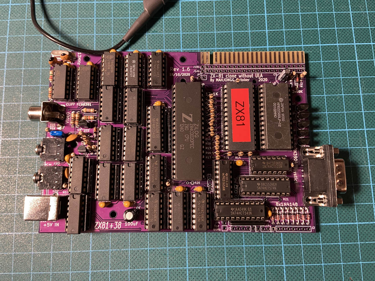
The assembled PCB for the ZX81+38.
Anyway, it was easy enough to find decent images of the original keyboard online, but I was still missing the exact dimensions. So I asked for help on Forum64 and received it very quickly, just as usual. My idea was to use cheap 6x6mm tactile switches and to create a custom PCB for the keyboard like Mahjongg had done before, but to improve the optics and ergonomics a little by adding a 3D-printed grid and a laminated cover.
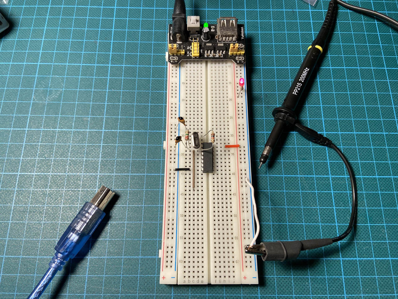
Next, with all required parts having arrived, I assembled the PCB for the ZX81+38 — and then could not get it to function. Nothing but a black screen. After a short search, I noticed that the board did not properly generate the clock signal for some reason.
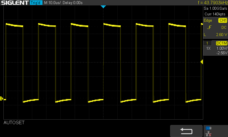
This was not quite the precise 13MHz clock signal I expected.
The crystal and its circuit should have produced a stable signal at 13MHz. But instead, I measured an unstable square wave around 40kHz. I replaced the crystal and tried different Schmitt trigger ICs without any success. Next, I even replicated the clock generator circuit on a breadboard where it worked just fine.
Generating the signal on a breadboad – not a problem.
Finally, I noticed that I had taken the values of the two capacitors for the clock generation circuit from an earlier version of the project’s BOM and used 15pF for C1 and C2. The latest version however suggests a value of 4.7pF for those two, instead. With the two caps replaced, I finally got the correct clock signal on the board and the unspectacular but expected screen display!
Finally! The expected welcome screen.
Back to the keyboard part of the project. My PCBs had arrived in the meantime and I had only small reason to be frustrated because of the footprint for one of the pin headers that I had managed to place the wrong way around.
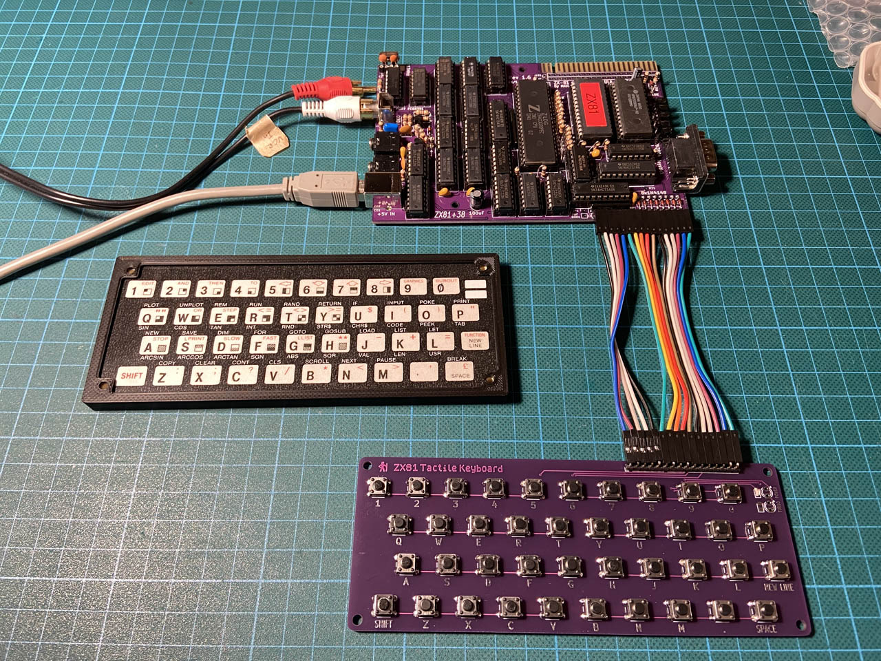
Twisted cables required for rev.1 of the keyboard to fit.
Oh well, nothing that couldn’t be worked-around for now by twisting a few Dupont cables.
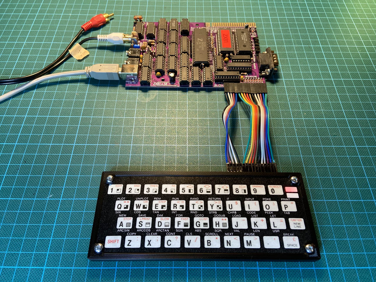
The external keyboard for the ZX81 in action.
With the keyboard generally working, it was time for the last phase of this replica project: a complete and new case for the ZX81+38 computer. It took a couple of iterations and half a spool of filament until I was satisfied with the result.
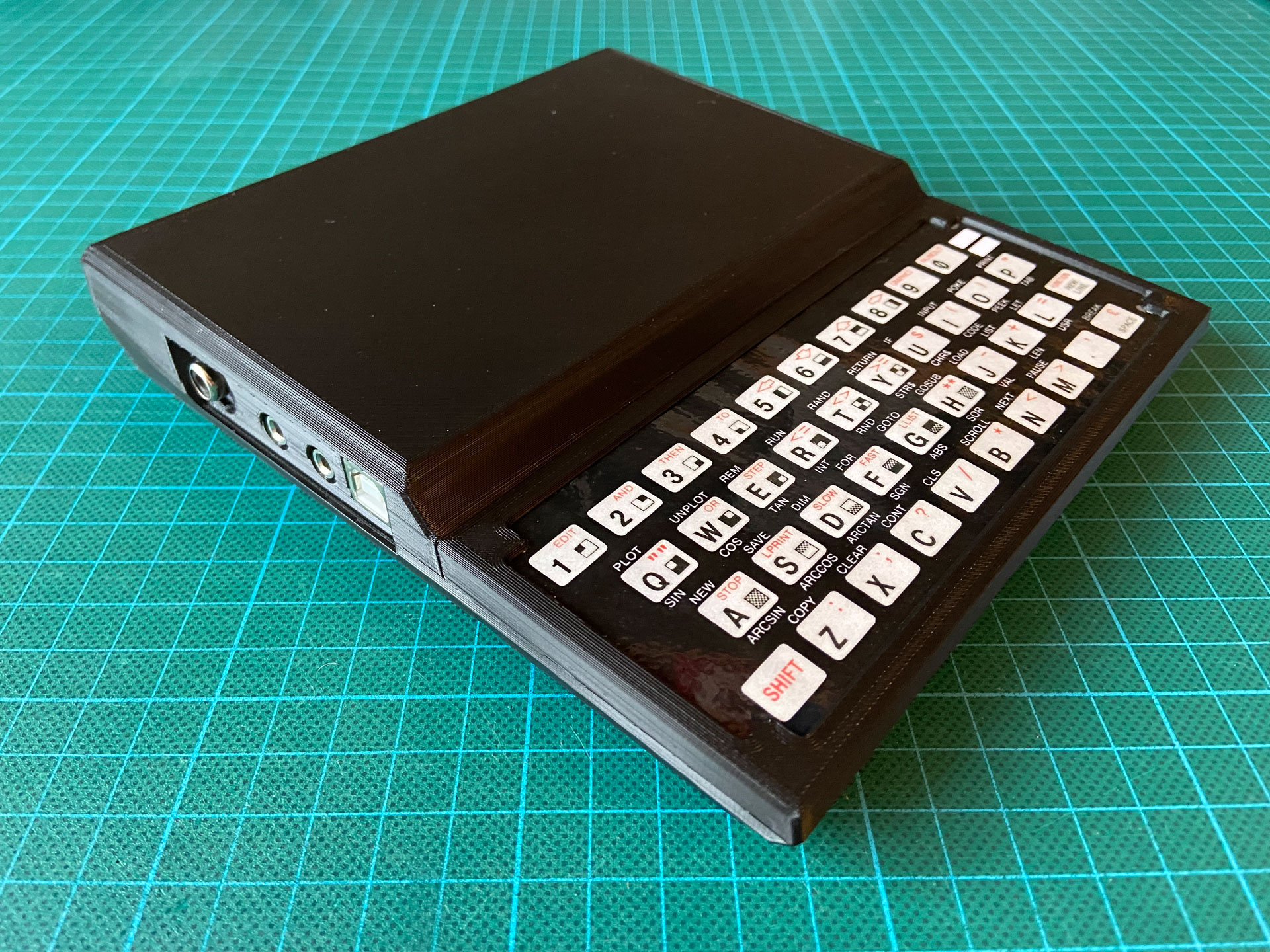
Finally, it looks like a real home computer.
This looks and feels like a real home computer from the 80’s now. You’ll find more photos in the image gallery below.
Next, I would like to load and run some “real” software. I’ve read somewhere that this should be possible by connecting a modern laptop computer to the cassette input. Also, I will clean up my project files a little so that I can share them in case anyone else wants to build this beauty. In short, I might do a follow-up post on this one but it might take a while — keep an eye out.
Update 2022-01-06
I have now sorted and published all design files needed to build this replica:
- The PCB for the keyboard can be ordered directly on PCBWay (see below).
- The KiCAD project files are available on Github.
- The STL files for the case and the external keyboard can be found on Prusa Printers and on Thingiverse.
- Of course you will still need to build the ZX81+38 PCB itself.
Update 2023-08-29
It has been brought to my attention that the keyboard connector layout was revised in revision 1.9 of the ZX81+38 motherboard. So I have made corresponding changes to the keyboard layout and inverted parts of the connector on the keyboard PCB (again). The updated layout is now available as Rev.3 on PCBWay.
The previous layout is also still available and is better suited for revision 1.6 of the motherboard.


Hi,
Thanks for this!! I built a zx81 back in 1981 and it did not work but I took it to Motorola, and they hooked it up to the oscilloscope and it had a problem in the clock timer circuit too. The engineer complimented me on my solder job. Apparently it wasn’t my fault… so I sent it back to Sinclair and they just sent me an assembled one (with not as good soldering I noticed Lol). So its a cool coincidence. I still have it in the box it was sent to me in. I want to build a pink one. I’m transgender and pink is my favorite and I can say that now: THANKS!! Stephanie Romer
Hi,
Thank you so much for your work I had a ZX80 in the 80’s and I also had issues with the clock but what a load of fun.
Recently I purchased an original ZX Spectrum not working and built a modern ZX Spectrum Harlequin.
Both are working after a lot of effort, now I am building a ZX81+35 like you have and will modify my parts list for the clock modification, thanks for the tip.
After playing with the Spectrum’s I cant wait to build the ZX81, they are a real lot of fun and the software was fantastic considering the limitations programmers had back then.
In closing anyone who is a computer enthusiast should own one of these classic computer, they have a soul and will put a smile on your face.
I’m glad you liked my post and thank you very much for the kind feedback!
Hi. How did you make the keyboard Inlay? Laser printer?
Yes, I used a color laser printer and a cheap hot lamination machine to make the keyboard inlay.
The problem with the crystal oscillator is simple, I should not have used a 74HC14 hex inverter, as the schmitt trigger input makes oscillation of this circuit very unlikely due to the high input swing needed, a normal 74HC04 or even better a 74HCU04 works much better, and then the values of the other components becomes much less critical.
Yes, the mirrored connector for the 5-line keyboard data connector is another mistake, and finally I should not have used a mix of logic, all logic should have been HC logic, but as you have discovered it works with mixed logic families as well.
All there and other errors have been resolved in revision 1.8 that can be found on GitHub.
Yes, the revision 1.6 PCB is not perfect, and at the very least you should only use 74HClogic, and the oscillator cannot be a 74HC14 (hex schmitt trigger inverter) it must be a 74HC04, or the oscillator will not run.
Its also better to invert the Z80 clock, due to a timing issue which might or might not affect your ZX81+38. Better yet use a revision 1.9 PCB. not the revision 1.6 one.
for the RCA connector use the original Cliff FC68391, other resellers sell crap connectors. that look the same but are worthless junk that break the moment you try to plug the cable in.
I love the case and have printed a couple. Thank you, its awesome. There does seem to be a fitment issue with zx81+38 version 1.10. 1.10 had some hole adjustments so it doesn’t perfectly line up. Also the keyboard included with the zx81+38 does not work with the current case. If you are interested in making changes for version 1.10 and its keyboard I’m more than happy to send you the 1.10 PCBs.
Hi Jay,
Thanks for your feedback! A while back I already made adjustments to the case for PCB version 1.9, where a couple of mounting holes were moved slightly. I never got around to publishing those files, because I couldn’t try them myself and I didn’t get feedback from the person who requested those changes, IIRC. Can you tell if there were more changes between version 1.9 and 1.10 that would concern the case design?
The keyboard PCB included in the official repo does indeed not fit my case and it will not be supported. At least the version that was available when I created my case wasn’t usable for this purpose, so I created my own keyboard PCB to go with the case. (See above.)
Addendum: I just took another look at the keyboard included in the official repo. The positioning of the push buttons doesn’t even match the original keyboard membrane.
The keyboard is way off, but I get the difference and why it wouldn’t be supported. It would be hard since it’s size is a bit bigger and there are no screw holes.
For the 1.10 holes the blog entry “68. moved a few screw-holes, for rev 1.10” talks about the 1.10 change. I’m more than happy to test, I also would be willing to try and do the keyboard work. I have access to Autodesk inventor.
Hello, my friend made for me updated case for Plus38, v1.10, with holes matching the new PCB.
You can download it at Thingiverse and print.
It matches 100% the v1.10 PCB.
https://www.thingiverse.com/thing:6657492