Expansion port expanders are adapters which allow multiple cartridges to be attached physically to the C64 at the same time. In rare cases, two of those cartridges will then be usable simultaneously, for the majority of cases the expander allows the user to switch between them.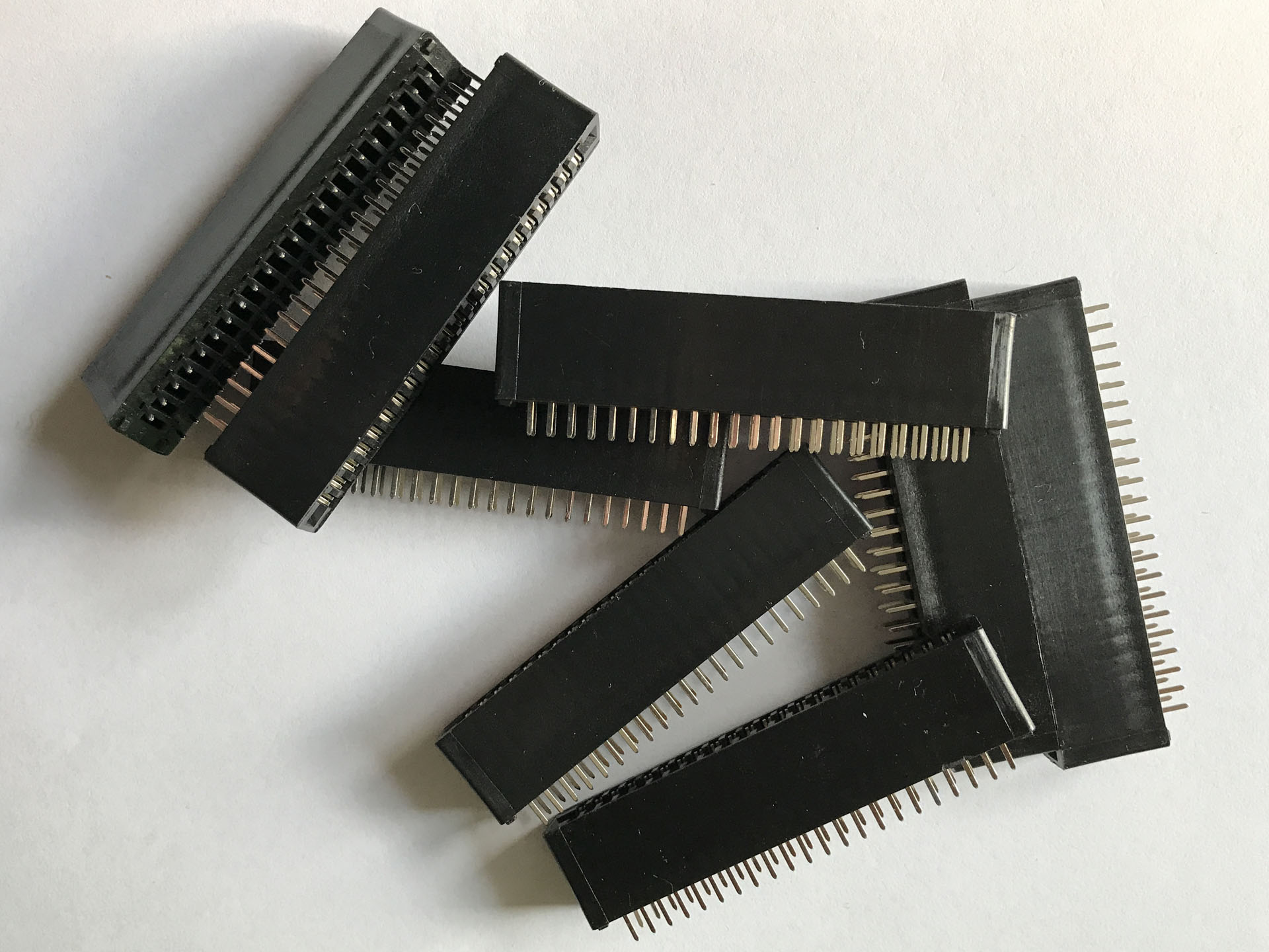
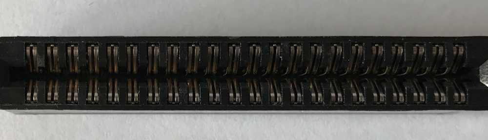
I’ve never owned one of these devices but I’ve been toying with the idea to create my own for a while. Recently then, a generous person donated a bunch of 44 pin board edge connectors that would be required to build it. So I started to take a closer look at existing implementations, from the past and present.
Here is what I’ve found so far, in no particular order. Unfortunately, I don’t have any photo material myself, so brace yourselves for a wall of text.
Datalux SV-703
The Datalux SV-703 is a very simple, purely mechanical device. It features 3 cartridge slots, a switch and a reset button. Here is a teardown video by GadgetUK164:
The 3-way switch will simply toggle the 5V, GAME, and EXROM lines between the sockets. This simple construct seems to cause all sorts of compatibility issues.
Aprospand-64
The Aprospand-64 features four cartridge slots and a slide switch next to each of them. According to the manual, those switches allow each cartridge to be “turned on and off”. I’m not sure what this entails exactly, because I haven’t been able to find out anything about the inner workings of the Aprosand-64 yet. Please post in the comments below if you know more or if you can provide photos of the PCB.
The Aprosand-64 does have a reset button of course and it also comes with a 1A fuse that is supposed to protect the 5V power lines.
CMD EX3
| 1 | +5V |
| 2 | +5V |
| 3 | GAME |
| 4 | EXROM |
| 5 | IO1 |
| 6 | IO2 |
| 7 | ROML |
| 8 | ROMH |
The CMD EX3 and the closely related EX2+1 are mostly mechanical solutions, too. Each of the three expansion slots has a set of 8 DIP switches that allow individual signal lines to be connected or disconnected.
In addition, one of the connectors allows the IO1 and IO2 lines to be flipped using jumpers. Then there is the obligatory reset button, of course.
X-Pander 3
The X-Pander 3 made and currently still sold by RETRO Innovations looks closely related to the CMD EX3 and it is even introduced as “heir-apparent” to the CMD device. Like its predecessor it features 3 slots, each equipped with an array of 8 DIP switches for switching the same 8 signals listed above. Most notable difference seems to be the ability to “swap” IO1 and IO2 on two of the sockets.
There is a resistor network close to each DIP switch, consisting of seven 10k pull-up resistors each as it seems. Those weren’t used on the CMD EX3 and I’m not entirely sure which lines these are connected to. Judging from the VIC-20 variant, I would guess it’s the signal lines but what is the intention?
Datel EX64
The Datel EX64 is another 3-slot variant (also see here). A fuse, a single sliding switch on the side, a reset button, two 74LS367 hex 3-state buffer ICs, three power LEDs, and a 74LS04 hex inverter.
At a quick glance it looks like the 74LS367’s are used to switch the GAME and EXROM signals between the sockets and the 5V rails are switched mechanically. Nothing else. But I could have missed something.
Cardboard/5
As the name implies, the Cardboard/5 features five cartridge slots and lots of Blinkenlights LEDs. For each slot there are two DIP switches. One of them will enable both EXROM and GAME lines for its slot, probably through the adjacent 74LS38B1 quad 2-input NAND buffer. The other one toggles the 5V power supply. Then there is a fuse and a reset button, of course.
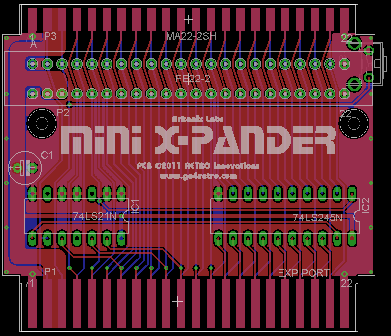
Mini X-Pander
The Mini X-Pander is a little different. It features two cartridge sockets, one facing up and the other one straight on to the back. There doesn’t seem to be a way to switch any of the signals between the slots, however. Besides the reset button, the small PCB also carries two logic ICs: a 74LS245 octal bus transceiver and a 74LS21 dual 4-input AND gate.
The 74LS245 is used as a driver for the 8 data bus lines, presumably to improve signal quality and to make certain cartridges function that would otherwise be causing problems. Looking at the board layout, I can see that the DIR pin of the LS245 is controlled by the R/W signal from the C64. The AND gate is used to disable the bus transceiver if IO1, IO2, and ROML are all high. To what end, I do not yet know…
64’er Modul-Port-Umschalter
Also of a different kind is the “Modul-Port-Umschalter” (cartridge port switcher). Build instructions were published in the April 1994 issue of the German magazine “64’er”. This board is intended to complement the mechanical expanders mentioned above. One of these devices is supposed to be inserted into each expansion slot, between the actual expander and the cartridge.
Each “Modul-Port-Umschalter” uses ten (!) 74HCT4066 quad analog switches to connect or disconnect a total of 38 different lines. In addition, a 74HCT125 quad 3-state buffer/line driver is used to to drive the GAME and EXROM signals going from the cartridge to the C64.
Others
There are of course other expanders that I didn’t have time to investigate yet or that I failed to find reliable information on, e.g. the FB-3XP and the Rear Admiral XPorter.
Conclusion
Looking at the range of devices, there seems to be consensus that switching the GAME and EXROM lines is the bare minimum that an expander needs to offer. I would have had doubts whether to actually switch the 5V power rails because I’d be afraid of parasitic currents then powering cartridges through other lines. Most solutions seem to do this however — maybe to prevent cartridges from actively using the bus lines.
Additional lines that might be worth switching seem to be IO1/IO2 and ROML/ROMH. There is a bunch of different logic ICs being use to assist with the switching. I would still have to find two different boards that are actually using the same type.
So, lacking some actual hands-on experience with some of those boards or at least some exact and reliable reports from others on compatibility, it remains hard to judge how I should construct my own expander.
To answer a few of your questions:
I believe the Aprospand switches POWER to one or more cartridges, under the assumption that an unpowered cartridge will not respond to cart requests. This may have been true back in the ’80s, but any unpowered cartridge that wires 3V3/5V tolerant CPLDs today in such a slot will likely damage the CPLD. (Xilinx for sure, which includes the EasyFlash 3, but Altera might be affected as well)
The CMD EX units took a maximum configurable direction with putting a switch on all control signals. BTW, the CMD units do have resistor packs. They are in blue to the right and immediately above each set of switches in this pic:
https://www.forum64.de/index.php?thread/43983-c64-cmd-ex3/
The EX devices can also swap IO1/IO2 (those are the jumpers in the middle of the board), though I think one can only swap 1 slot.
Claim to fame: I was sent the first EX-3 to review, and I suggested in the review that the last slot should be pointed backwards to allow large carts to exist on the expander. Shortly after the review, CMD started offering the EX2+1
X-Pander-3
As noted above, the resistors are the same on the CMD items. They tie each unselected IO line to +5V when the switch is not active for that line.
I designed the Mini-XPander as well (hence the name), and the unit was designed after some folks found that the cartridges like the 64NIC did not work well in the C128.
At some point, someone brought some vintage “advertising carts” to a VCF-ME show. THese carts had room fro a number of EPROMs and would cycle through ads for businesses using C64 GFX. We assume they were placed in businesses back in the day. Some of the carts came with a little add-on card that looked to clean up the signal lines. Someone took this little add-on card, found it fixed the 64NIC+ issues, and so asked that the design be redone. Hence the Mini-XPander. The new design added the second slot, the reset button, and I think it also handled both IO1 and IO2, whereas the initial design only handled 1 of them. However, note that this design does not support DMA activities, so things like the REU and accelerators like the SuperCPU and TurboMaster will not work.
In my opinion, your first design should be a passive design withour ICs. It’s easiest to get working. Switch at minimum GAME and EXROM.
Wow, thanks a lot for the extensive feedback! Many valuable insights and interesting bits of history on the subject. It’s very much appreciated!
Wouldn’t other expanders, in addition to the Aprospand, have the same problem with damaging 3V3/5V tolerant CPLDs, if one switches the GAME and EXROM signals on and only switches off the 5V power to cartridges to turn them off?