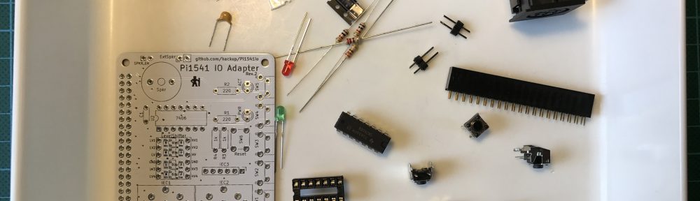
On Friday, I received the prototype batch of PCBs for the second revision of my IO Adapter for the Pi1541 project. Today, I finally found the time to assemble a couple of those boards and so far, everything seems to be working great!
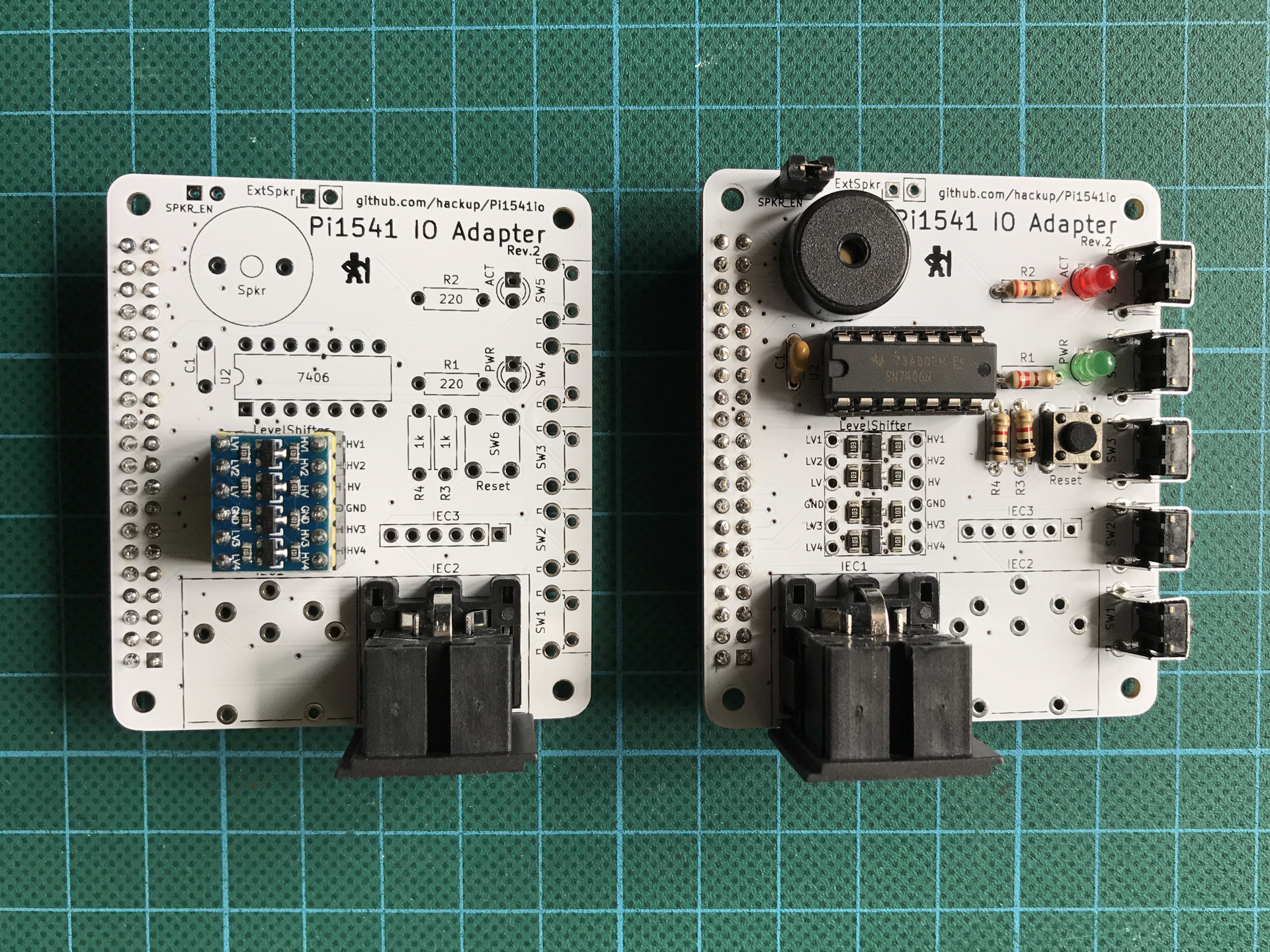
Two working configurations of the Pi1541 IO Adapter.
When assembling one of the rev.2 boards, there are multiple alternative configuration to chose from. One of the simplest working ones — shown on the left side in the photo above — needs only three components: a 6 pin DIN connector, a 4 channel level shifter module, and a 40 pin female header to connect to the Raspberry Pi. Most of the possible configurations can be built using easy to solder through-hole components, only!
The Level Shifter
All configurations require voltage level converters. The PCB layout allows you to either use a cheap and ready-made 4 channel module or to fit the same SMD components that the module contains directly to the board.
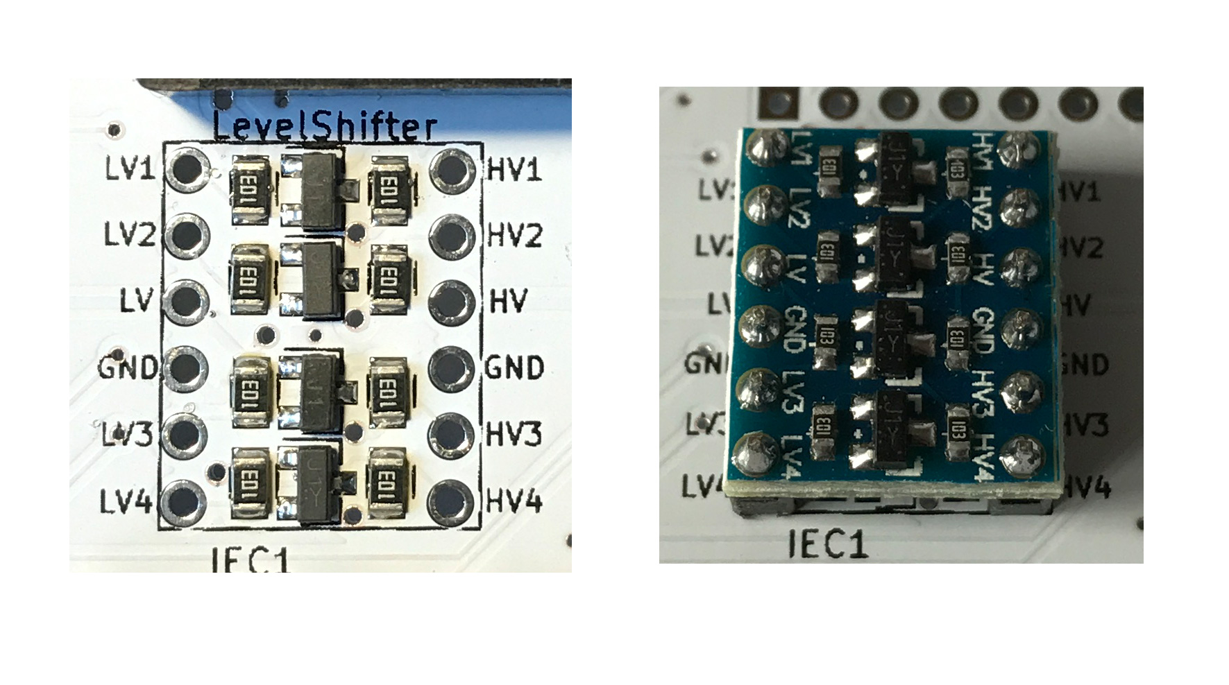
Voltage level converter options: SMD components directly on the PCB (left), or a ready-made module (right).
Technically it doesn’t make a difference which one you chose. Using the module will relieve you of the need to solder SMD components in case you are hesitant to handle those.
The Bus Driver
On his project page for the Pi1541, Steve White currently describes two different options for wiring the Pi1541. “Option A” simply uses a 4 channel level shifter to connect the Raspberry Pi to the Commodore serial bus. This works fine, but you risk damaging the RasPi when connecting three or more devices to the bus. “Option B” requires an additional 7406 logic IC to drive the bus. The Pi1541io board must be configured for one of these two options using solder bridges on the bottom side.
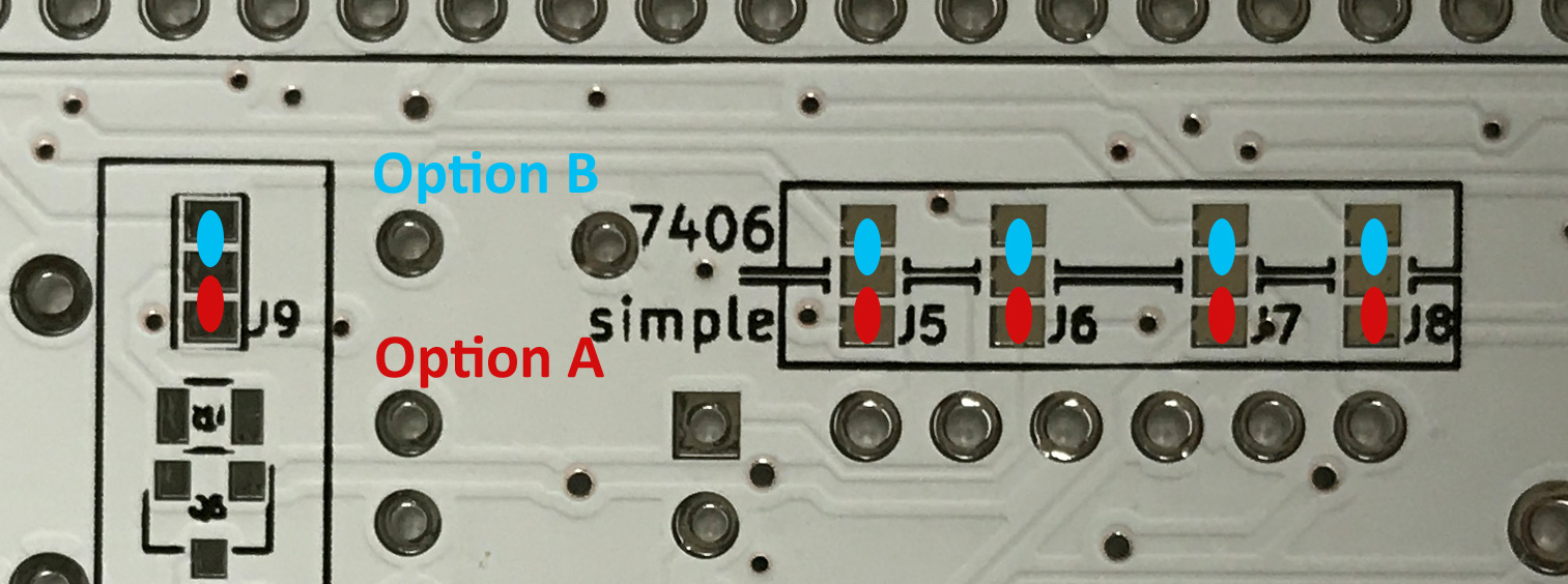
Configure the bus driver using solder bridges.
Note that you also need to tell the Pi1541 software which bus driver you are using by changing the options.txt file. Please see Steve’s instructions on how to do this. If you configure your board for “option B” the following components are required:
- 7406 logic IC (U2)
- 100nf bypass cap (C1)
- two 1kΩ pull up resistors (R3, R4)
With “option A” these components are not required.
The SRQ Signal
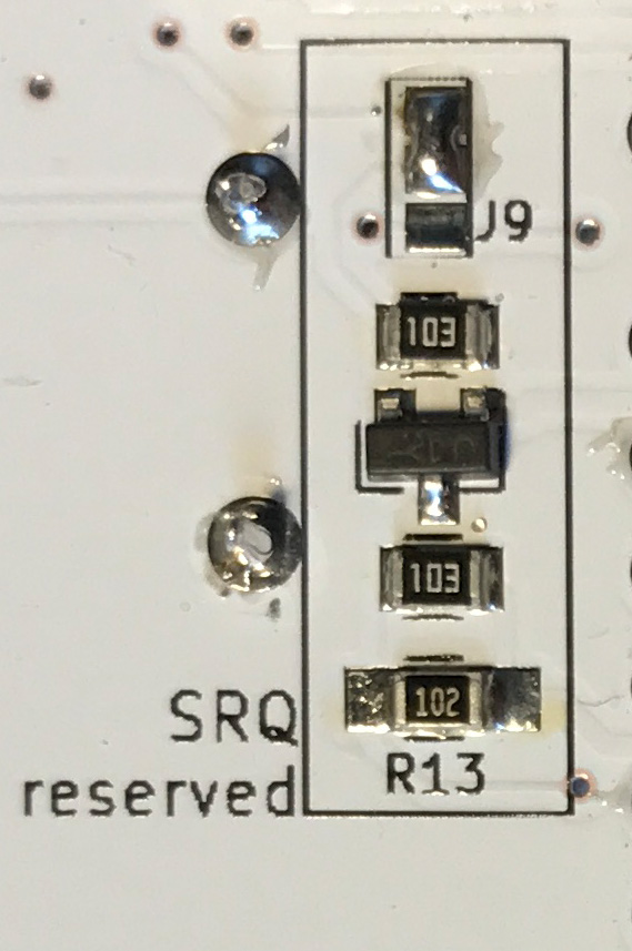
Also on the bottom side of the PCB there is a place for components to add an optional 5th level converter channel that connects the SRQ signal from the serial bus to the Raspberry Pi. This signal is not used by the C64 and currently it isn’t used by the Pi1541 either. So, there is no need to fit those components now.
Other Components
Most of the other components are optional too, actually. Some of them are very useful though, like the 5 push buttons. Others are probably better left our for now, like the piezo speaker. I would recommend to fit at least the two LEDs with their resistors and the five push buttons SW1-5.
This is the current BOM updated from the first revision:
| 1 | P1 | 2×20 pin female header | eBay |
| 1-2 | IEC1-2 | 6 pin DIN socket | eBay |
| 5 | SW1-5 | right-angle push buttons | eBay |
| 1 | U1 | 4 channel level shifter module | eBay (China) eBay (Germany) |
| 1 | U2 | 7406 IC | eBay (China) eBay (Germany) |
| 1 | C1 | 100nf ceramic capacitor | eBay (China) eBay (Germany) |
| 1 | SW6 | push button (optional) | eBay |
| 1 | D1 | 3mm green LED | |
| 1 | D2 | 3mm red LED | |
| 2 | R1,R2 | resistor 220Ω | |
| 2 | R3,R4 | resistor 1kΩ | |
| 5 | Q1-5 | BSS138 FET SOT-23 | eBay |
| 10 | R5-12, R14, R15 | resistor 10kΩ, 0805 SMD | |
| 1 | R13 | resistor 1kΩ, 0805 SMD | |
| 1 | piezo speaker (optional) | eBay (China) eBay (China) | |
| 4 | M2.5 screws, 18mm | ||
| 4 | M2.5 nuts | ||
| 4 | distance rolls, 11mm |
In addition, you’ll still need a Raspberry Pi 3B or 3B+, a micro SD card, a good power supply, and a Commodore serial cable.
What next?
I will distribute the remainder of my prototype batch of PCBs to people on Forum64 for further testing like I did the last time. I would actually recommend to wait for those results to come in. If you absolutely cannot wait any longer to try this yourself, here are the Gerber files for you to download. As always: use at your own risk. I’m not responsible for any damage you might cause to your hardware, to yourself, or to anyone else.
Update: For those of you who’d like to order PCBs for revision 2, you can do so directly on PCBWay.


Really nice!
Will you consider seliing assembled boards?
Thanks for your feedback! But no, I’m currently not considering selling assembled boards.
looks amazing and really clean. Is the plan to sell the boards and if so, do you have a idea for when they might be available?
Waiting for kits to assemble then!
Just wanted to say thanks! This is a great looking board. I have ordered all the parts I need to build 5 of these. Glad to see you get 10% commision on these by the way. Now just have this eternal wait for everything to arrive… Will let you know how it works out after all this stuff arrives and I get one up and running.
Hi William, I’m glad you like the boards! Let me know how they work our for you.
Hi,
Thanks for this PCB 🙂 My PCB’s just arrived from PCBWay.
I was just going to try Option A but I have a few questions.
Rather than use a DIN socket and then a lead, I was just going to wire in a short length of cable with a DIN plug. Can I wire straight into IEC3? I was going to open out the DIN PCB connector holes at the bottom of IEC2 (earth holes not signal!) and use a cable tie to secure my short DIN cable.
Could you tell me the PIN OUT for IEC3 Left-to-Right please.
Thanks
Hi Sean,
You’re welcome! That is exactly what the IEC3 connector is indented for. Except maybe for the cable tie thing but that should be ok, too. 🙂 The pin numbering is the same as on the Commodore IEC connectors and pin 1 is marked on the silk screen.
Best,
Christian
What’s the progress on rev. 3? 😉
The first prototype batch for rev.3 has been produced in China and is on its way to Germany. 🙂 Once I have those boards, I’ll assemble one and post the results.
Hi,
I got it all assembled. Only issue was I put in the LED’s the wrong way around to start with!
Here is a pic: http://tinypic.com/r/25hn950/9
Thanks
Well done! And thanks for the picture!
Excellent work and it looks great! Does rev. 3 have a header for the display, it looks like its soldered to the header pins of the RPi directly.
Which case are you using and does the top fit when the shield is attached?
I just ordered the parts and can’t wait to order the pcb when its ready. Thanks for putting this out in the open 😀
Thanks, I’m glad you like the board! Rev.3 does have a connector for a SSD1306 I2C OLED display. But all pics on this page are showing rev.2 right now. I hope to receive the rev.3 prototype batch later this week so I can post an update. If all is well, I will release the updated layout too, of course.
As for a case, personally I haven’t had time to worry about that yet.
Is there currently a way to order a bare board?
Hi Christian,
Thank you so much for sharing this board! I had five made and assembled the first one as Option B this week. The Pi-hat configuration is very elegant and it works!
https://drive.google.com/file/d/1SUhWAjX8lKiXFOekOxW5kqcNNbNYucse/view?usp=drivesdk
I will be building a few more to sell on as complete units, hope that’s okay. I used to build XE1541 cables in the early 2000s and as both a CBM and RPi fan, I couldn’t resist having a go.
Thanks again!
Yes, there is: just search for Pi1541io on PCBWay.
Pingback: Pi1541io Revision 3 | hackup.net
Got my boards from PCBWay a couple of days ago. (The last parts I needed that shipped). Still waiting for the rest of the components I need, guess they are on the slow boat from China lol. Have you figured out the voltage situation for the SSD1306 I2C OLED display on the version 3 boards yet? I have 2 of those coming as well, straight forward enough to connect to these boards but I’ll most likely order the v3 boards when you have this figured out. By the way I really like PCBWay, ordered 2 different boards and got 2 extras on both!!
Rev.3 hast 5V on the I2C header which will cause problems if you use the wrong display module. I wrote an other post about this recently. So, I’ll probably skip rev.3 and publish a new rev.4 instead with 3.3V on the header.
What is the correct orientation for the LED’s?
KiCAD’s silk screen symbol for the LEDs is indeed less than optimal. On this board, the cathode (shorter lead) goes into the square hole. If you look closely, you can see that it is connected to the ground plane.
Sehr Schade, dass hier alles in englisch gehalten ist.
Pingback: Pi1541io Revision 4 | hackup.net
Does this have, or will it have, any support for the 1571, or 1581 and D71 or D81 images?
The Pi1541 software is currently emulating the hardware of a 1541, only.
Someone sold me one of these on ebay. It works fine until I actually try switching disks. I suspect they knew there was problem too. Any idea what might cause this? For example, booting Test Drive then it asks to flip disk and press enter. I go to raspi and select the second disk and it just sits there. Other apps like GEOS do the same (closing disk, switching to another, then trying to open it). Was wondering if any incorrect set up of option B would cause this.
Just wanted to let you know I finally got this up and running and they work fantastic! 2 months I waited to get all the parts I needed!! (It takes Canada Customs that long to process these small packages, a week to get here from China, then sits in a cargo container for up to 2 months before it gets processed. Next time I’ll pay for shipping!!!). One small thing I’d like to point out, there is no silk screen indicating +/- for the speaker. No big deal as it was easy enough to figure out. One small request, could you put up a pic of the schematic of the board as well. I used an online gerber viewer to follow the traces but a schematic would have been easier to read. Not really necessary for this version, but for ver 4 or any future ver, it would be handy. I now have 4 fully assembled and tested units, with a few spare boards. I can finally retire my SD2IEC as these work much better even with the fast loaders I have tried so far!
Thanks again, very happy with the results, William.
Thanks for the feedback, glad you like the project. I added a PDF of the schematics to the repo now.
Quick question of clarification. I’m ordering the components for Rev.4 board. I take it that these SMD compoents which are used for the surface mounted level shifter (Q1-4 and R5-12) are not needed if we decide to use the ready-made module instead?
Also, are the SMD compoents for the 5th level converter (R13 – R15), that is used for SRQ, required to be soldered on as well for the board to proper operate?
Q1-5 BSS138 FET SOT-23
R5-12,R14, R15 resistor 10kΩ, 0805 SMD
R13 resistor 1kΩ, 0805 SMD
I’m looking forward to building this once all the parts get in. Awesome work on making Pi1541 I/O board.
Thanks for putting up the schematics, very helpful indeed! As much as I love the look of the white boards it is very difficult to follow the traces (especially with my old eyes lol). Thought I’d mention that I screwed up one of the bridges on the first board I worked on. Lifted the pads as I forgot to turn down my iron, I’ll blame that on old age 😉 Easy enough to fix that though anyhow and no big deal as they sent a couple of extra boards anyhow. Will try to give away a couple of boards to friends and maybe sell the others, then I’ll order some ver 4 boards (unless you plan on another revision?) I only ordered 2 of the SSD1306 OLED’s and have yet to hook one up. Surprised at how small they actually are. I may just order something larger to make it easier to read. At any rate, I’m off Wed so will hook one of these up then just to see how they look.
Thanks again, William
Yes, you need either the SMD components OR the level shifter module. The 5th level shifter is currently NOT required as SRQ is not used by the software. It might be used in the future, e.g. if someone manages to emulate a 1571.
Hi! Thanks for a VERY nice project. The PCB is beautiful.
Got my PCB’s last week. 20 of them! Got almost all the components and the oled display as well.
Anyhow, got a somewhat stupid question (without checking the schematic), do you use the square solder pads for the LED anode?
There seems to be some kind of anarchy among designers whether they use the square or round pads for the anode and cathode.
At least from googling I see contradictive meanings about it.
I have already soldered the anode to the square one, so I cross my fingers I won’t have to desolder them again.
Thanks for any answer,
I’m using the standard KiCAD footprints for the LEDs and I agree that they can be confusing. With these footprints, the square pads are connected to GND so that’s where the cathode should go. Sorry about that…
Thanks for the answer!
Darn, I saw the schematic just right where the outline symbol is clear on the placement now and then back to now to read your comment.
But I googled a bit more, and it seems as though the most common thing is just what you have here, so it’s just me doing things way too impatiently. 🙂
Ah well, guess I’ll just have to desolder. Should be very easy with those diodes.
I have ordered the level converter boards (rather not solder SMD’s), but I had a couple older ones lying around at home. But then I noticed that they had different dimensions. So I guess the ones that fit the hat are supposed to be 13×15 mm.
Then I’m scratching my head a little about what distance height I should use for the female display connector. Because I guess if it is too short the display will cover the reset button.
The location of the display connector that was somewhat hastily added in rev.3 is less than perfect. In rev.4 it is still best suited for a short Dupont cable inside a case for the entire Pi1541. There is actually a rev.5 of the board that moves both reset button and LEDs from “under” the display. I haven’t published this revision in the past because it will no longer fit the 3D printable case available on Thingiverse but it still lacks support for the upcoming features that Steve is working on for about half a year now. I might publish rev.5 soon though because it is unclear when that tape support will be available…
Just building 5 pieces of these wonderful rev4 baby’s and having two questions:
– Am I’m right that one can use *two* of the 6 pin DIN sockets (IEC1 *and* 2) to daisy chain the bus? For example C64pi1541io1541
. Is a Rpi 2B sufficent?
Yes, you can fit both IEC1 and IEC2 just like on an original 1541. If you connect additional devices, using the variant with the 7406 IC is recommended to protected the Pi, though. Please check the Pi1541 project page for information on which Raspberry Pis are currently supported.
Thanks for the reply. Yes, forgot to mention that I’m building variant B (with 7406). Well, this will be a killer device 🙂
Many thanks for sharing this project!
Pingback: 1541pi and Raspberry Pi 0 W 1.1 | NewRetro.OO.gd NewRetro.OO.gd