| Update: For those of you who can’t wait and who understand the possible issues described below, rev.3 boards are now available on PCBWay. If you can wait another 3 weeks I’d recommend you wait for the next revision.
|
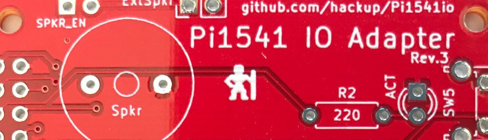
After a longer wait, today I finally received the prototype batch of PCBs for revision 3 of the Pi1541io board. Only relevant change to the previous revision is the I2C header for connecting a SSD1306 based OLED display module.

Consequently, the BOM is mostly the same. When assembling the board, you need to make your choices and configure the solder bridges as described for revision 2. Additionally, you need to configure the I2C header using new solder bridges if you intend to use it.
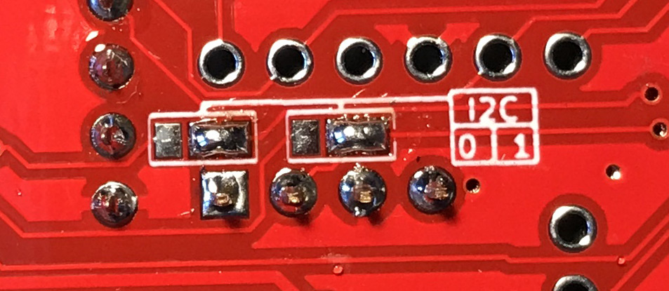
Configure the I2C header.
If you configured your board to use the 7406 IC as a bus driver, you have the choice between using I2C bus 0 or 1 of the Raspberry Pi. If you opted for the “simple” layout without the 7406, you are limited to using I2C-0.
There is one issue with this revision of the board: The OLED modules I had available feature their own 3.3V regulator and I assumed that this would be the case for all such modules. So I didn’t want to cascade this regulator with the one on the Raspberry Pi. That is why the supply voltage on the I2C header is 5V.
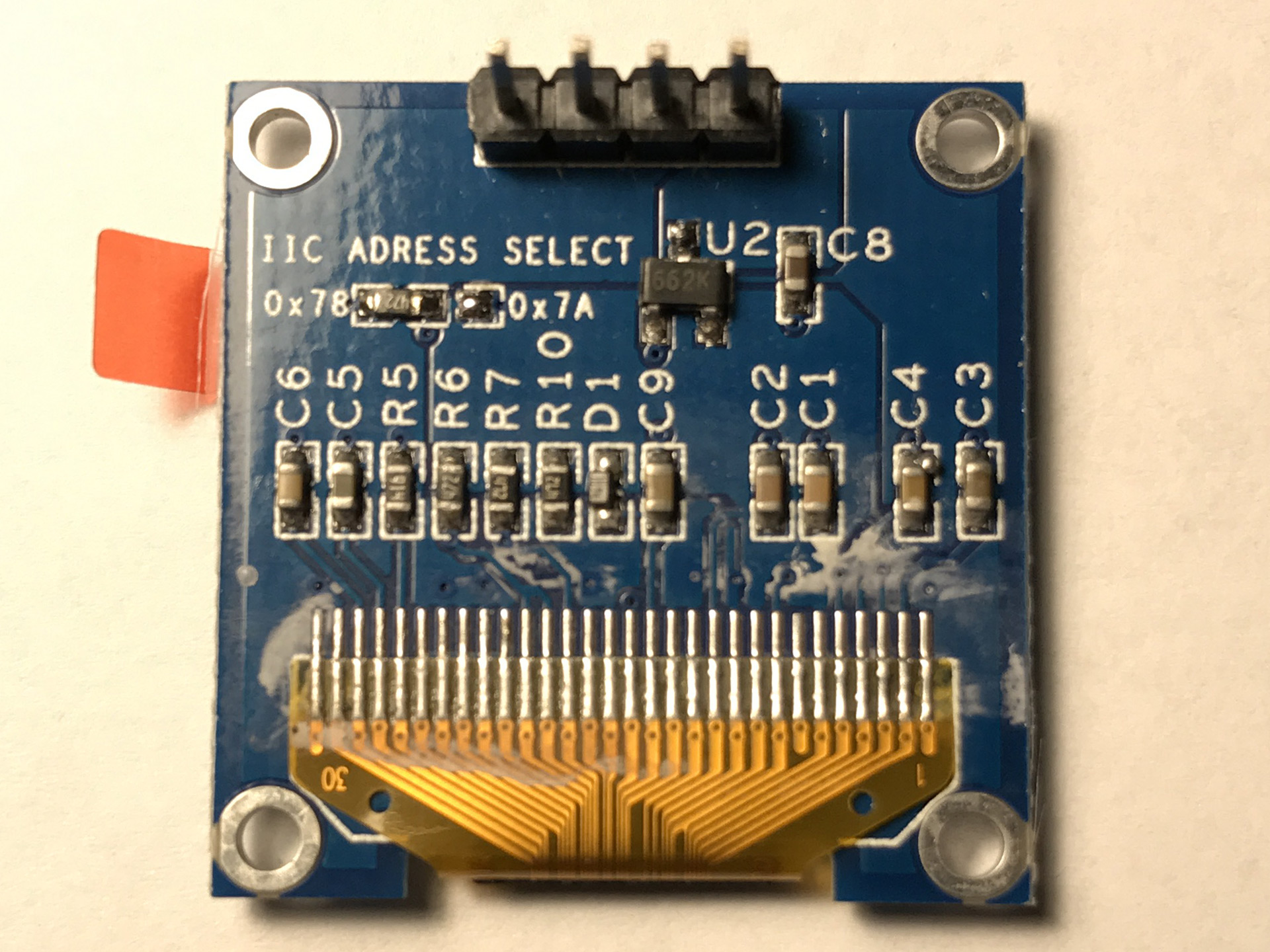
3.3V regulator on the OLED display.
This means you must only connect display modules that bring their own voltage regulator. Those are usually specified for a voltage range like 3V to 7V. If the module does not have a regulator, you will run the SSD1306 at 5V, most likely damaging the module and the Raspberry. Sorry about this, I guess it’ll be fixed in revision 4 then…

So, when shopping for a display module make sure it satisfies all of the following:
- SSD1306 controller
- OLED display with 128×64 pixels
- I2C Interface
- Voltage regulator included, i.e. specified to work at least on 5V
- Pin order: Vcc – GND – SCL – SDA (if you intend to plug the module directly)
This is still all work in progress, so use at your own risk.


Hey CG,
Thanks for designing the board!
Are you going to upload the Gerber’s for Review 3?
jayo
Yes, I will upload the Gerber files for revision, too! Might be a couple of days before I find the time, though.
🙂 looking forward to it, cheers
jayo
Thanks for the updated board, currently building a couple of V2 boards and was going to hard wire the display in myself but might go for some V3 as well.
I have a question about the display pin outs. You look to be using the same display as I have but mine has the pin outs as GND VCC SCL SDA where as your board is showing VCC GND SCL SDA. Im not doubting your work but are they definitely correct. If so it might be worth adding to the text that the builder needs to make sure the display has the same pin out as shown on the board.
Just following on from my previous comment, i can see on your photo of the display there are different types of connector. Definitely needs a warning about checking display to make sure voltage is right way around
There are display modules with both pin orders around. I would recommend to wait another couple of weeks for the next revision of the board. Revision 4 will feature additional solder bridges allowing you to choose the order of the power supply pins.
Which software Gerbers came from? KiCad maybe?
Maybe full project (including native data) could be publicated?
PS. Why do you use PCBway? PCBway has a really expensive shipping cost? I prefer elecrow:
https://www.elecrow.com/pcb-manufacturing.html
The KiCAD project files are available on Github.
I have used Elecrow before and they are ok, too. Just like AllPCB or JlcPCB. Shipping costs don’t differ much when you choose comparable methods. In this case, I didn’t want green PCBs. Elecrow will charge extra for that.
how about adding a dxf of the board to enabe a 3d model to be created ?
lee