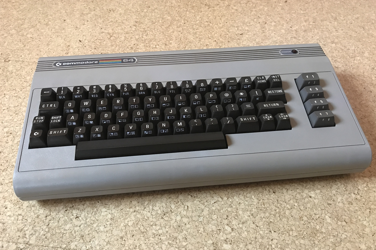
Commodore 64 “breadbox”.
Recently, I retrieved a Commodore 64 “breadbox” version from my parent’s attic that was given to me by a friend in the early 90s. As I recall, it wasn’t fully functional even back then. It would halt as soon as a program tried to play any sound. But when I connected it now and powered it up, all I got was a black screen.
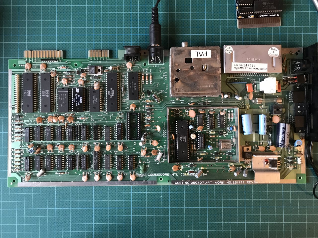
The broken ASSY NO. 250407.
I took it apart completely, even the keyboard, in order to give the case and all the mechanical parts a good cleaning. Then I went on to see what I could do to fix the “ASSY NO. 250407 REV.B” motherboard that I found inside.
Remove the SID first.
First thing I did was remove the MOS 6581 sound chip (aka. SID) at U18. It was likely to be fishy (see above), it was socketed on this board anyway, and a C64 will usually run just fine without it. And if it turned out to be fine after all it wouldn’t be in danger of getting damaged during the repair. But even without the SID nothing had changed, I still got a black screen.So I went on to check a few basics. I used a multimeter to make sure the power switch was working properly and I checked the 5V DC and 9V AC voltages at “the other end” of the PCB on the user port, as well as the 5V and 12V DC produced by the two additional power regulators. Everything was within the expected ranges.
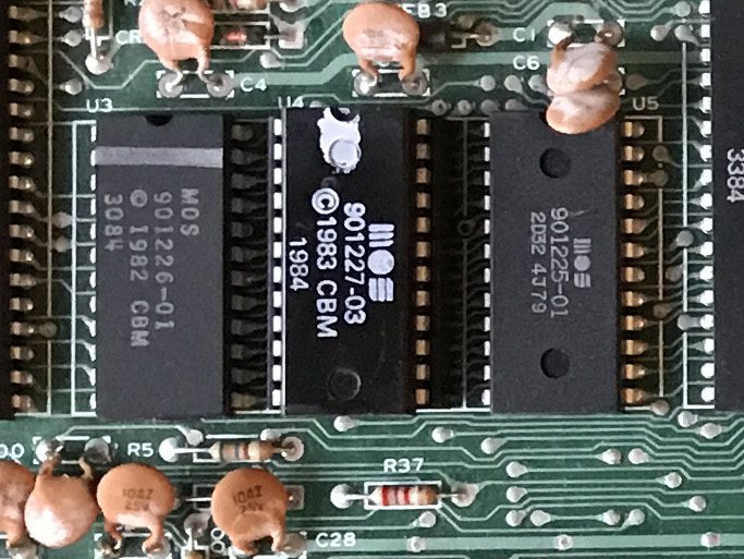
The Basic, Kernal, and Character ROMs (from left to right).
After the board was powered on for a few minutes I tested if any of the ICs would get exceptionally warm or hot, simply by touching all of them with my finger. The graphics chip felt quite warm but actually not much more than expected. But the Kernal ROM chip U4 also felt hot which I wouldn’t have expected.
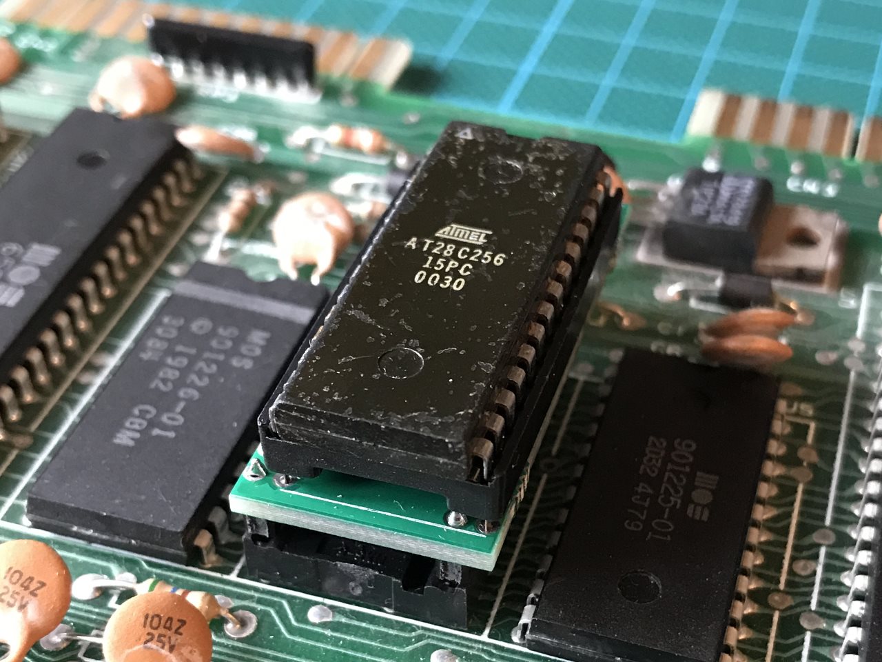
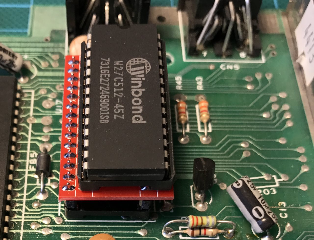
EEPROM in adapter board in socket U4.
So, this was my next guess then, the decision made easy by the fact that U4 was also already socketed. I soldered an adapter board that would allow me to replace the 2364 ROM — a MOS 901227-03 in this case — with a more modern 27C256 EEPROM I had in stock. After burning the the Kernal image to the chip I pulled out the original ROM, replaced it with the new contraption, and power everything up again: Just a black screen.
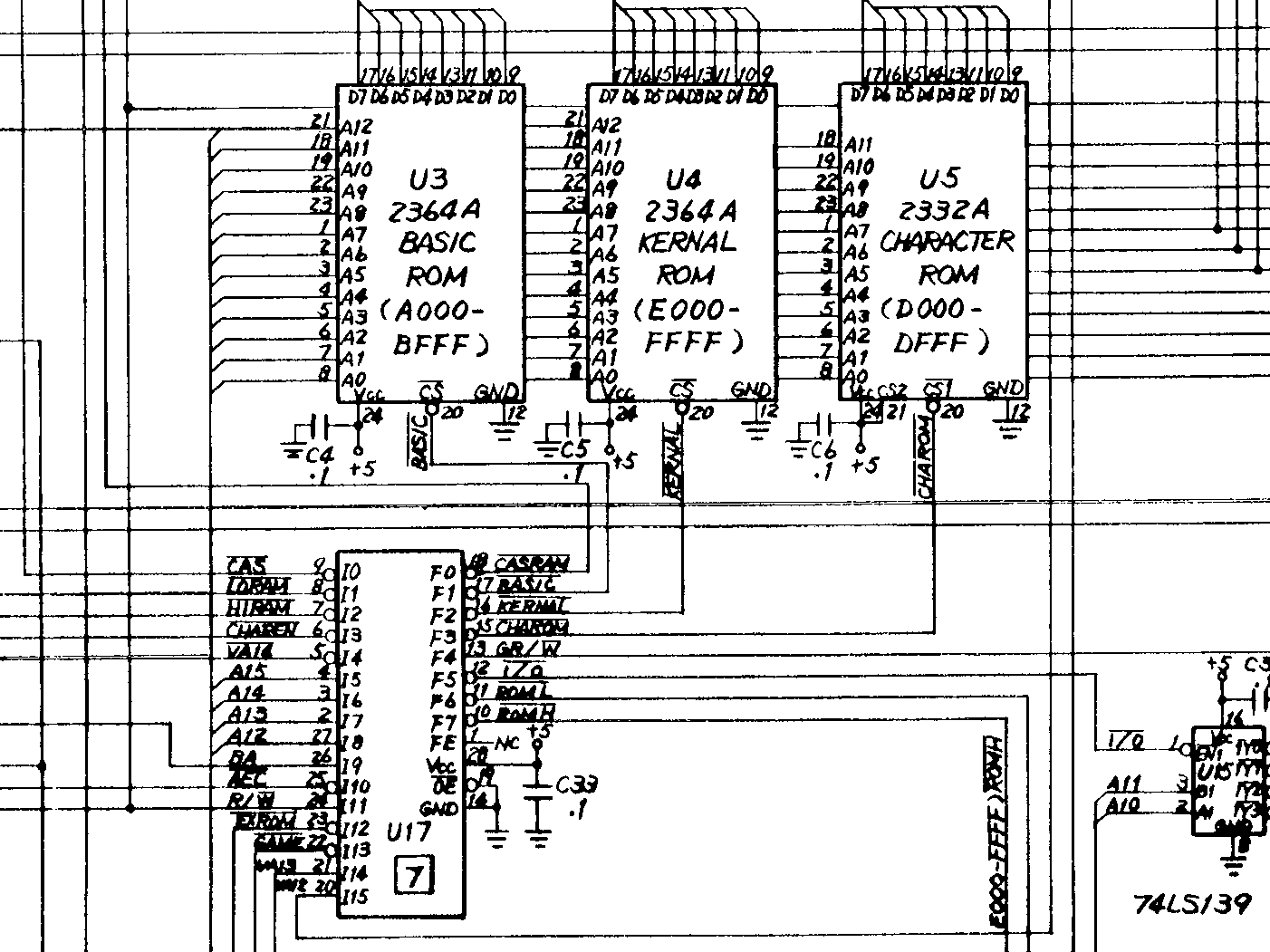
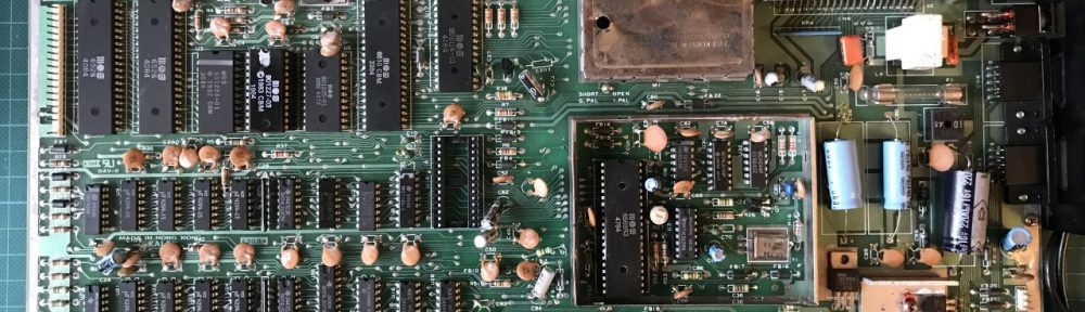
Schematics near the ROM chips.
I still felt that I should have a closer look at U4, so I set up my cheap Hantek 6022BE USB oscilloscope and examined the pins on that chip. The signals coming to the address pins and those on the data pins didn’t look suspicious: Somewhere between 0 and 4.5V, square(ish), and at frequency around 1Mhz. But the CS signal on pin 20 was obviously wrong, the voltage varied only roughly between 0 and 1.7V.
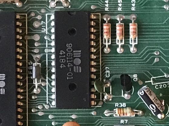
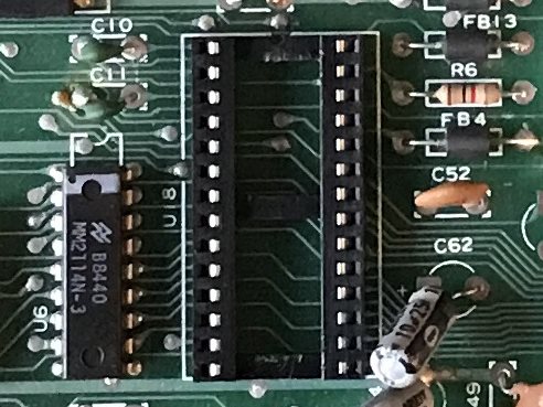
The notorious PAL.
This signal is coming from the PAL chip at U17. The PAL is a specialized logic chip that regulates access of all the other components to the address and data buses. And it is notoriously known to fail and die in these old machines.
Unfortunately, the PAL is much harder to replace properly than the ROM chips. It is obviously no longer being produced and its internal timing is critical. Still, at its core, it is a device that maps 16 input bits to 8 output bits. Just like a 64kb parallel ROM. So, there is a way to replace it with a different adapter board containing yet another EEPROM programmed with the right data. Reportedly, this solution is known to fail under certain circumstances and there are other, more complicated and expensive alternatives.
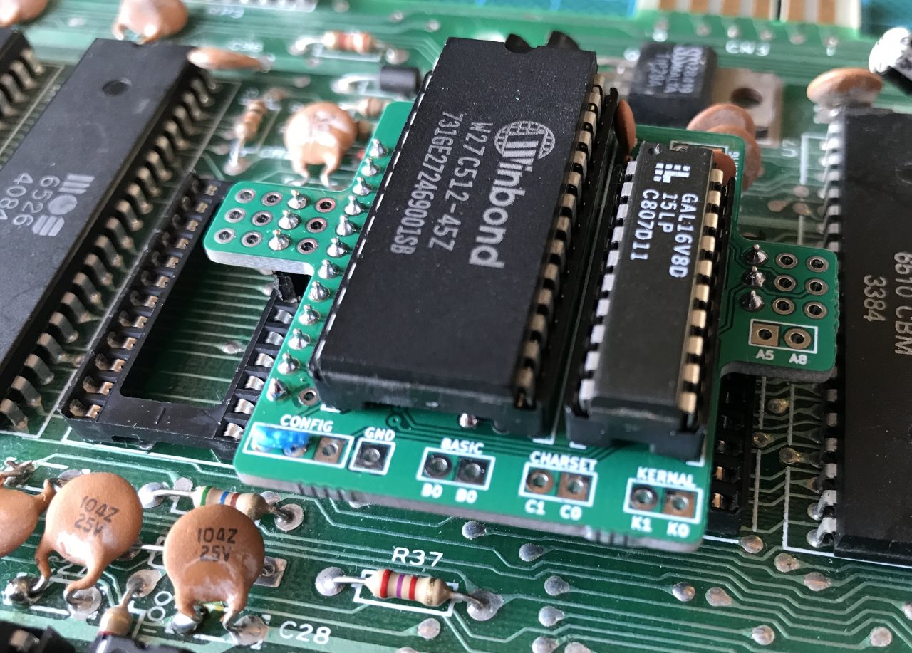
The replacement PLA.
But for me, it was just the right thing, because I had again everything in stock that I needed to build such a replacement PLA. So, I desoldered the original PLA, soldered an IC socket in its place, and installed the pseudo-PLA. Connect a display and power up the board:
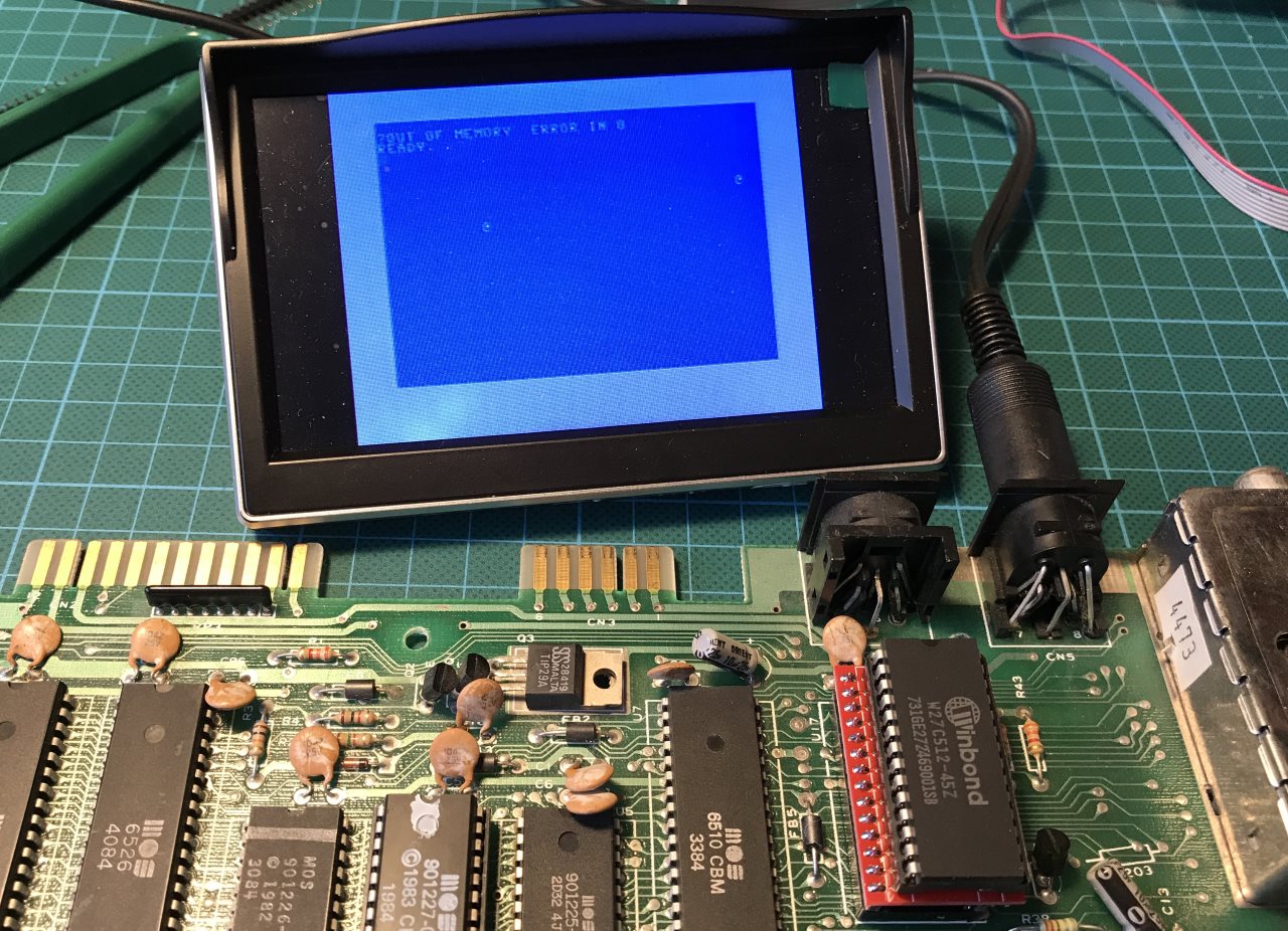
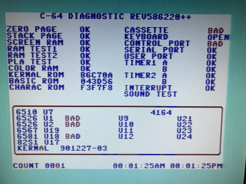
A first sign of life.
Still not quite what I had hoped for but definitely a step forward! This now looked very much like a RAM problem and my Check64 diagnostic cartridge confirmed this. The “dead test” program signaled that U11 was defective. I did not have any replacement RAM chips in stock, however. Compatible DRAM chips are becoming increasingly hard to get. So I finally ordered five of those, thinking that I might need a few spares in case U11 wasn’t the only one.
First DRAM chip replaced.
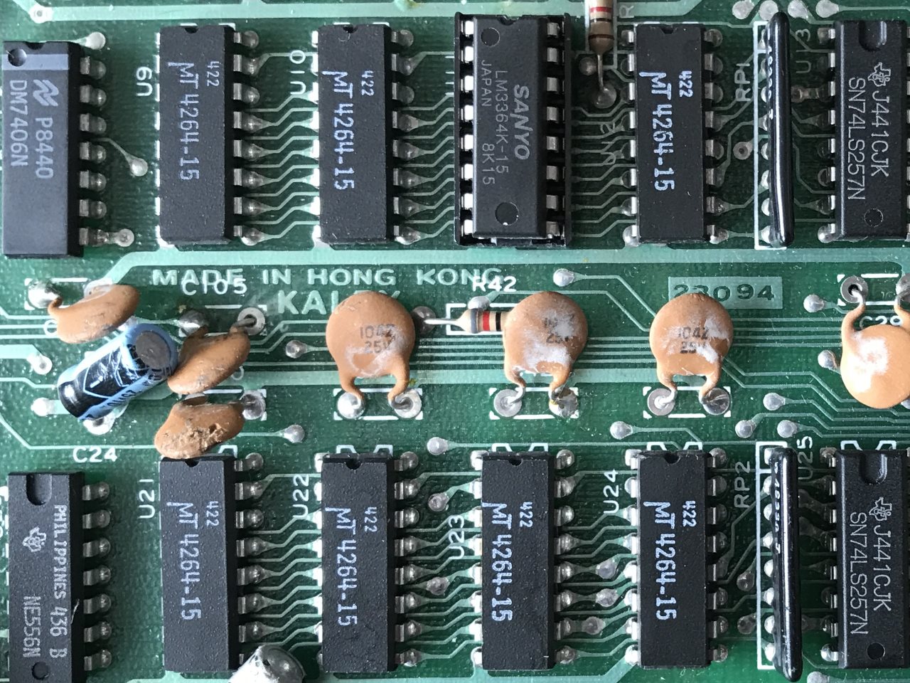
Stupid mistake. After the DRAM chips arrived, I socketed and replaced U11 — only to be told by the cartridge that another one was broken, too. And then the next one and so on. In the end, I grudgingly had to place a new order for more Sanyo 4164 DRAMs as all 8 chips needed replacing. And while I was at it, I also ordered an assortment of logic chips that might also be at fault, just to be sure.
Bad RAM everywhere.
Thus, I had some time to spare while I waited for my second order to arrive. So I desoldered the remaining two ROMs, the Basic ROM U3 and the character ROM U5 in order to replace all 3 ROMs with a single Reprom64 adapter. I had those PCBs made in advance a while ago.
Reprom64.
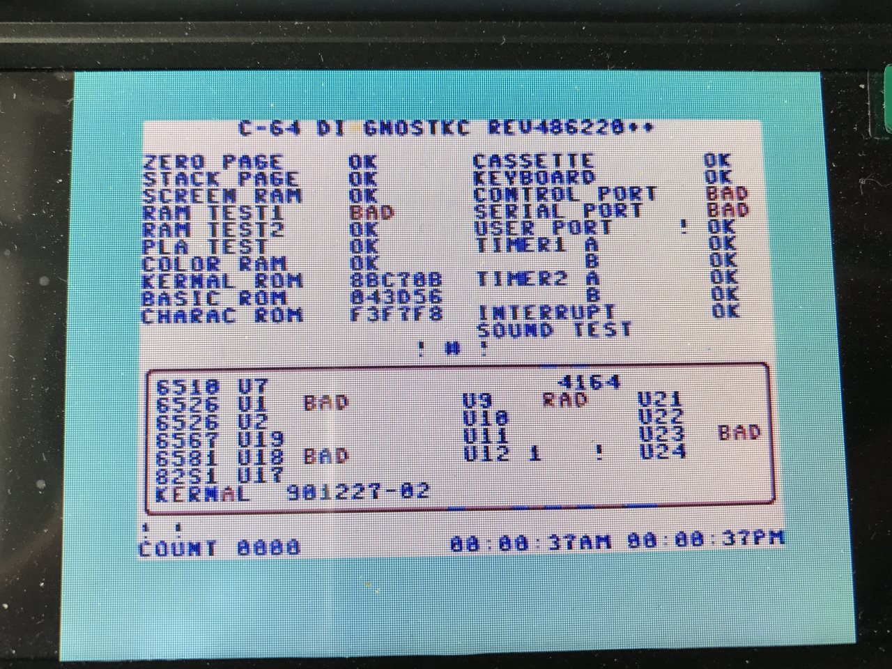
When I had finally replaced the remaining DRAM chips with “new” ones, the diagnostics cartridge finally diagnosed a healthy system. Healthy except for two remaining issues. For one, some random letters of the diagnostics output seemed to be colored wrong.
Red letters at random places.
There has been some discussion about this. There could be something wrong with the VIC, the static color RAM or the glue logic between. Or this could be a side effect of the pseudo-PLA I installed. But then I tried various other software, games, demos and the like and I couldn’t reproduce those color problems anywhere. So I’ll leave it at this for now.
The other remaining issue of course, is the defective and now missing 6581 sound chip. As it happens, there is an interesting option to replace the SID chip, the SwinSID originally developed by Swinkels. This device is based on an overclocked Atmel microcontroller that emulates most of the sound synthesis features of the original SID. What a great excuse for more tinkering!
Tolaemon did a great job of describing how to build your own “nano SwinSIDb“. While ready made Gerber files are available on his page, I felt like getting some more KiCAD practice myself. So I designed my own board based on the schematics and had it made and shipped from China.
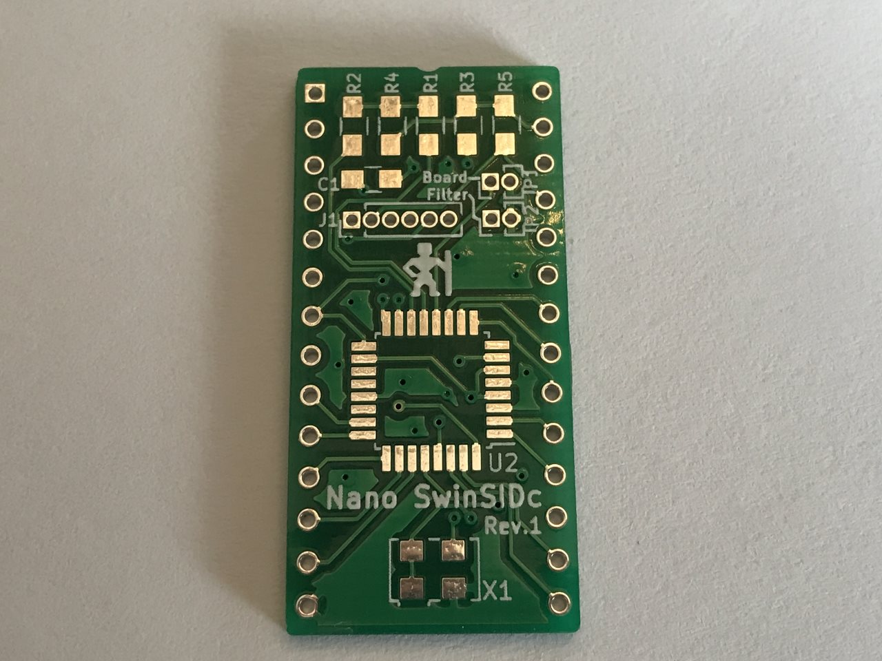
A new SwinSID board.
There are a few minor issues with this first revision of the board, like accidentally mixed up jumper labels and a hard to solder footprint for the oscillator. I’ll share the KiCAD project once I get around to fixing those issues in revision 2. I couldn’t find a suitable 32Mhz oscillator that was specified for 5V, so I tried a XO53 that is actually supposed to run on 3.3V. It seems to be working fine so far! Neither the overclocked controller nor the oscillator are getting the least bit warm. And the sound the SwinSID produces sounds good to my ears at least.
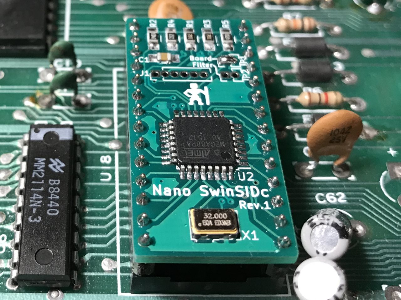
Nano SwinSIDc assembled and installed.
All in all, this has been a lot of fun! A thrilling puzzle, many new and old things learned, the warm and fuzzy feeling of nostalgia and a sense of achievement when the silicon veteran was up an running again. My biggest problem now: I would love another puzzle of this kind and I have a bunch of spare parts left. But I don’t have another broken Commodore motherboard.
Pingback: Retro Repair, Addendum I | hackup.net
Pingback: C64 Mainboard Assy No. 250425 "Repair" | hackup.net
Pingback: Super Zaxxon Replica | hackup.net
Pingback: The XCPLA – Yet Another PLA Replacement | hackup.net
Hi,
there is new SID Replacment named armSID
this one is almost 100% combatible 🙂