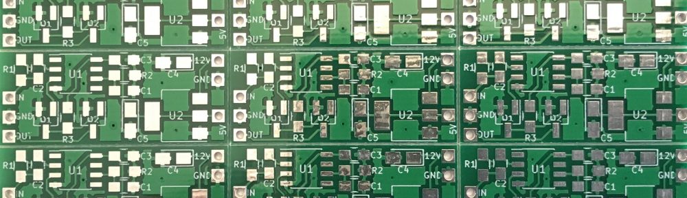
Following the first prototype of the LM1881 based SyncFix64 I made a few minor changes, improving the schematics and layout. Then I was ready to order the first batch of properly manufactured PCBs. The boards took a little over two weeks for production and shipping.

This was also my first try at ordering a v-cut PCB panel and I’m quite satisfied with the result considering the resulting low price per unit. I assembled one of the boards tonight and the device is working properly. So I assume the whole batch should be fine.

The project files for the updated version 1.1 of the SyncFix64 are available on Github and here is the list of required components:
| C1,C2,C3 | 0805 | 100n |
| Q1,Q2 | SOT-23 | BSS138 |
| R1 | 0805 | 100r |
| R2 | 0805 | 680k |
| R3 | 0805 | 10k |
| U1 | SOIC-8 | LM1881 |
| U2 | SOT-223-3 | AMS1117-50 |
| C4,C5 | 1206 | 22µF |
Update: There are German assembly instructions available for download now.


Hi do you possibly sell the pcb or a kit of this, I am facing the same problem.
I have a few kits left over and some more PCBs. Please send me an email if you are still interested. Shipping costs might be an issue though, depending on where you are from.
I have received your email but I could not reply because Hotmail has (wrongfully) blacklisted my mail server. I have requested to be removed from the blacklist but that will take time. Alternatively, if you have another (non-Microsoft) email account you could email me again. Sorry about that.
Pingback: SyncFix64 Revisited – What about the VIC-20? | hackup.net
Hi, I have build your syncFix using throw hole component on a protoboard to connect my c64 to a cheap parking TFT monitor.
To avoid to use 12 volt to supply the TFT monitor I have removed the DC to DC converter (in my case a XL1509 ) from the TFT pcb.
I have slightly modified your schematic:
– removed R3 10k
– change R2 680k with 1k
After this changes the screen is very clear and and works fine with my c64.
I have not yet tested it with my vic20 because of I have to build an AV cable but I will try
Hello.
I have a PAL C64C (Shortboard) with an RF Modulator replacement circuit.
There was a dark bar across the screen with the default components, looking a bit like interference.
Having looked at the LM 1881 datasheet, it would appear that adjusting R2 fixes this problem (related with frequency).
I used a 1M pot to tune out the bar in place of R2, then soldered in a permanent SMT resistor. In my case, this ended being a 470k ohm one.
Cheers.
It works fine now.
I haven’t had these issues myself but others might have. Good to know that there is a solution. Thanks for your feedback!
Any chance you still have one for sale? I am building a cynthcart synthesizer with integrated monitor. The cheap car LCD’s have issues with the c64 pal video signal. I read your invention solves this!!!! I can solder basic projects but the these small surface mount components are a challenge. A ready made syncfix would be awesome. Greetings!
While I do have a few left over kits that I originally prepared for people on forum64.de, I cannot offer ready made modules, unfortunately. Mostly for legal reasons.