The prototype batch of PCBs for revision 4 of the Pi1541io board didn’t take long to ship and it arrived from PCBWay while I was on vacation. Today, I finally managed to assemble one of the boards and everything seems to work great!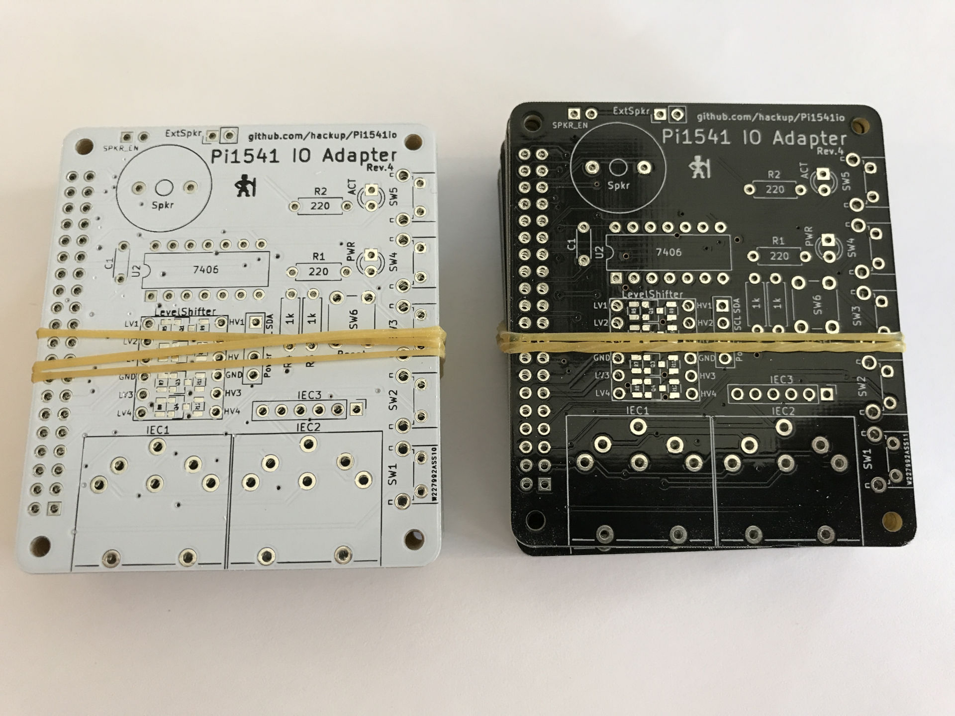 Revision 4 is basically what the previous one should have been: an improved rev.2 with an added I2C connector for an OLED display. In this revision though, the I2C connector can be configured to accommodate different kinds of display modules.
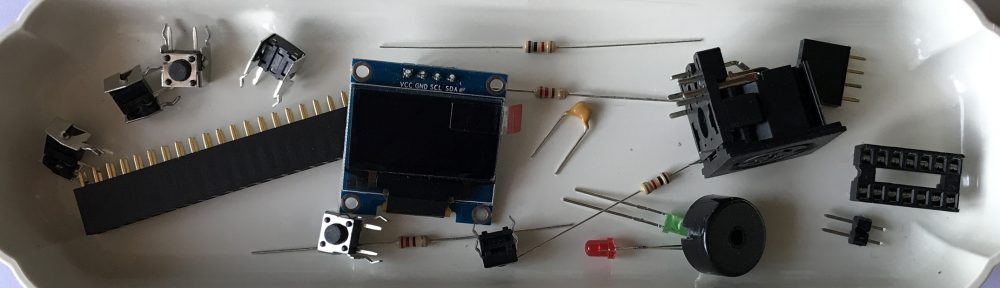
Again, the BOM for this board is mostly identical to that of revision 2. But I’d recommend you get yourself a compatible display, too.
| 1 | OLED Display with I2C SSD1306, 128x64px | eBay (China) eBay (Germany) | |
| 1 | J12 | 1×4 pin female header | eBay (China) eBay (Germany) |
When assembling the board, you need to make your choices and configure the solder bridges as described for revision 2. Additionally, you need to configure the I2C header using new solder bridges if you intend to use it.
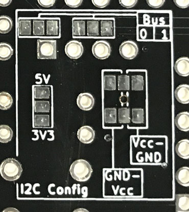
Configure the I2C header.
- Choose whether to power the display module with 5V or 3.3V. You must not use 5V if your display module is lacking its own voltage regulator! If in doubt, choose 3.3V — it should work in basically all cases.
- Configure the pin order for your display module. You need to choose between one of
GND-Vin-SCL-SDAorVin-GND-SCL-SDA. - If you configured your board to use the 7406 IC as a bus driver, you have the choice between using I2C bus 0 or 1 of the Raspberry Pi. If you opted for the “simple” layout without the 7406, you are limited to using I2C-0.
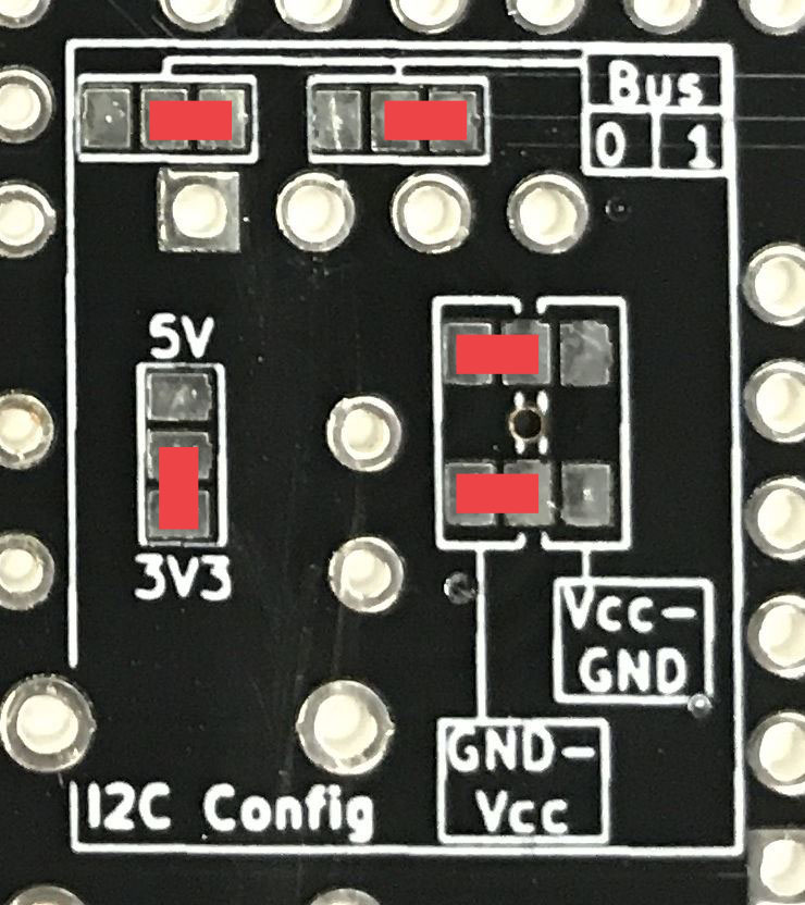
Example for a valid I2C configuration.
[Update] In the example image above, the I2C header is configured for 3.3V, I2C bus 1, and a display module with the pin order of GND-Vin-SCL-SDA.
 The project sources will again be available on Github as soon as I find the time to update the documentation. In the meantime, you can already order your boards on PCBWay, if you like.
Update: Sources and Gerber files for revision 4 are now available on Github.


Just found this project and it looks great. I just ordered some rev 4 boards from pcbway. Not really clear on how the solder bridges should be configured though. Do you bridge the left two pads top and bottom for GND-Vcc and the right two pads top and bottom for Vcc-GND pinouts? For bus 0 and bus 1 selection do you bridge all three pads? Thanks
You are right, that could be clearer. I should add an example photo or drawing to clarify. Yes: Left two pads top and bottom for GND-Vcc. No: Left two pads in both boxes for bus 0, right two pads for bus 1.
Can you share the Gerber files of revision 4?
PCBWay is ignoring my messages on Facebook so now I want to place the order elsewhere.
Yes, I will. The Gerber files will be included in the git repo. I still need to do some cleaning up there before I can push the latest changes, though. Maybe I’ll get around to that later today.
Can you share the Gerber files of Revision 4?
@Okurka: As I told you before, I will share the Gerber files. But pushing me will not speed up the process.
My first question nor your answer to it were showing when I posted my question a second time. I didn’t mean to push you, I simply thought my first question was blocked.
You Sir, are a legend. I built an OLED-enhanced Pi HAT based on your Rev. 4 board, which was a joy to work on and works flawlessly. Thank you so much for all your hard work here, you’ve made a lot of old retro-heads very happy.
Thanks Dan, I’m glad you like my board! But the praise mostly belongs to Steve for the actual Pi1541 project, of course.
I just hand-built a Pi1541 board, and while looking for case STL files found this board. I think I’ll order a set and make some for friends. 🙂
Hi,
I really appreciate all the hard work that went into this project. But do you see a Pi1541 Revision 5 in the near future or will Revision 4 be the last one for a while?
Thank you,
Gene
Hi Gene, I’m glad you like my project. Your question is not easy to answer. As of now, I don’t have any plans for a new revision. But the Pi1541 project itself is still evolving quickly. If new hardware options arise from this, there might very well be a Rev.5 of my board. And if anyone finds a major fault in Rev.4, there will certainly be a new revision. But the latter seems a little unlikely by now.
Great work! I’m planning to build a few of these and is about to order components. The DIN sockets I’m looking at* differ somewhat from the holes on your PCB:s; the two front “support pins” have a spacing of 5.08mm instead of 10.16mm. Would it be possible to add holes for 5.08mm spacing too to make other DIN connectors fit?
*DIN measurements:
http://oi64.tinypic.com/xlaxx0.jpg
Built this board with the exact same display and chips used in the example and photos. Would you share your config for it?
@Mackie: I actually considered supporting those “other” DIN sockets before. So yes, I could do that. But I am reluctant to broadly share a new layout revision that I have not tested before myself. If you agree to do this testing for me, I could supply you with updated Gerber files. Without any warranty of course, just like the rest of the stuff I share here. And I would need a few days to find the time for an update. Drop me a mail if you are still interested.
@Jeff: Do you mean sharing the options.txt file I’m currently using? Sure, here you go.
Thank you very much for this. I just finished building it and works perfect. It also made me realize my sight isnt what it used to be when trying to do the surface mount soldering haha.
Anyways, great work. If there is a rev5, would it be possible to move the reset button so its not under the oled screen?
Other than that amazing job! haven’t had any issues with it.
Thank you.
It would be fantastic if someone could design a 3D printable case for it. That would be the icing on the cake for this great project.
great work! I have it working for 95%. 🙂 With an original Serial cable, I am able to load PRG files using the browsing mode on the Pi1541 or with FB64. When emulating .D64 roms, the Pi1541 says ‘Emulating’ but my Commodore is not able to load the directory or the game. Any suggestions how I can fix that would be very welcome. Thank you in advance for your help.
Remote debugging is hard. You being able to use the browsing mode means that there is at least some kind of working connecting between the Pi and the C64. I would suggest you first double check your hardware to make sure everything is soldered and connected properly. Pay special attention to the configuration of the solder bridges. Next, also double check that you have prepared the contents of you SD card exactly as described on Steve’s project page. Does your options.txt match the hardware build option you have chosen? If your are still stuck then, you could describe your issue on the Pi1541 thread on the Lemon64 board. There are lots of people around that might be able to recognize the symptoms and help you.
I’ve build the option B board, configured the I2C jumpers as in the picture, except that I’m using bus 0, but I get no display. I’ve also tried bus 1 but same results. I’ve tried two different oleds from two different vendors and still no display. Voltage configuration is correct and measures correct, i2cScan reports 0x78, which is correct. Only thoughts are maybe config.txt needs something changing, so I have pasted what i though was the relevant part below. Any help with getting this working would be appreciated.
// If you are using I2C LCD you can optionally change what pins it is connected to.
// (defaults to 0 for non-split lines (Option A) or 1 for split lines (Option B))
i2cBusMaster = 0 //SDA – pin 27 SCL – pin 28
//i2cBusMaster = 1 //SDA – pin 3 SCL – pin 5
i2cLcdAddress = 60 // I2C display address in decimal and shifted. 60 == 0x78, 61 == 0x7A
//i2cLcdFlip = 1 // Rotate i2c LCD screen 180 degrees
i2cLcdOnContrast = 127 // Allows you to adjust the contrast on your i2c LCD screen
i2cScan = 1 // scan i2c bus and display addresses on screen
Hi Carl, have you set the “LCDName” parameter in you options.txt?
Ignore my post above, I failed to look in the obvious place and hadn’t un-commented ‘LCDName = ssd1306_128x64’…DOH!
@cg thanks
Hi everyone. I have also a problem with the ssd1306 oled (no display). I have build the option 2 with bus-master 2. The i2c-address is usually 0x3c. But 0x3c is 60 in decimal and not 0x78 (in the options.txt comment)?! Vin and GND allocation is ok. Can someone help me? Thx
// Sample options.txt configuration file for Pi1541
// If you would like to change the drive number then specify it here (8 is the default)
//deviceID = 9
// If you are using the split line hardware option (ie Option B) then you need to specify this option
splitIECLines = 1
// If you are using some type of hardware that requires the lines to be inverted then specify these options here
//invertIECInputs = 1
//If you are using a 7407
//invertIECOutputs = 0
// If you are using the Pi’s composite video out then these options allow you to experiment with the display resolution
//ScreenWidth = 512
//ScreenHeight = 384
// By default Pi1541 will search the root of the SD card for a ROM file and use this for ROM1.
// The first file found with either of the following names will be used; d1541.rom, dos1541, d1541II, Jiffy.bin
// You can override the default ROM1 by specifying it here
ROM1 = d1541.rom
// You can specify additional ROMS here (up to 7)
// You can then use the function keys (F1-F7) on the keyboard to change which one you would like to use (only in browse mode and not in emulation mode)
// You can also use the buttons to swap ROMs by holding down button 1 and pressing one other buttons 2-5
// .LST files can also specify one of these ROMS that will automatically be selected when the LST file is loaded.
//ROM2 = Jiffy.bin
//ROM3 = d1541II
// The rate (in seconds) a long selection is scrolled
scrollHighlightRate = 0.07
// Enable RAMBoard emulation – 8k drive RAM expansion at 0x8000
//RAMBOard = 1
ChargenFont = chargen // 8 bit font file
// If using CBMFileBrowser then it is best to specify this option. When the computer resets the Pi will always revert back to the root folder ready to load CBMFileBrowser again.
OnResetChangeToStartingFolder = 1
// If you use FB64 (CBMFileBrowser) and want to use a fast loader cartridge (AR6, EFL, FC3) to load it then use this option to automatically mount it.
//AutoMountImage = fb.d64 // You MUST have a disk image in \1541 with this filename
// If you are using a FB128 in 128 mode you can get FB128 to auto boot using this option
//AutoBootFB128 = 1
// If you are using a 128 you can auto boot anything using this option
// This over-rides AutoBootFB128
//128BootSectorName = bootsect.128
// If you would ever like to disable browse mode completely you can do so here
//DisableSD2IECCommands = 1
// This option displays the IEC bus activity on the bottom of the Pi’s screen
GraphIEC = 1
// If you have hardware with a peizo buzzer (the type without a generator) then you can use this option to hear the head step
SoundOnGPIO = 1
SoundOnGPIODuration = 1000 // Length of buzz in micro seconds
SoundOnGPIOFreq = 1200 // Frequency of buzz in Hz
// You can create 320×240 PNG files with the same name as your disk images. With this option turned on they will be displayed on the Pi’s screen.
//DisplayPNGIcons = 1
// If you would like to specify what file will be loaded by LOAD”*” in browse mode then specify it here
//StarFileName = somefile
// Alt-N creates a new disk image.
// Names are formed automatically as autoname001.d64, autoname002.d64 etc…
// change the base of the filename here
//AutoBaseName = autoname
// If you are using a LCD screen then specify it here
LCDName = ssd1306_128x64
//LCDName = ssd1306_128x32
//LCDName = sh1106_128x64
// If you are using a LCD screen and you would like PageUp and PageDown keys to work with it then specify this option
//KeyboardBrowseLCDScreen = 1
// change startup logo on oled – 1541ii or 1541classic
LcdLogoName = 1541ii
//LcdLogoName = 1541classic
//LcdLogoName = customfile.raw
// If you are using I2C LCD you can optionally change what pins it is connected to.
// (defaults to 0 for non-split lines (Option A) or 1 for split lines (Option B))
//i2cBusMaster = 0 //SDA – pin 27 SCL – pin 28
i2cBusMaster = 1 //SDA – pin 3 SCL – pin 5
i2cLcdAddress = 30 // I2C display address in decimal and shifted. 60 == 0x78, 61 == 0x7A
//i2cLcdFlip = 1 // Rotate i2c LCD screen 180 degrees
i2cLcdOnContrast = 127 // Allows you to adjust the contrast on your i2c LCD screen
i2cScan = 1 // scan i2c bus and display addresses on screen
//QuickBoot = 0 // faster startup
ShowOptions = 0 // display some options on startup screen
//IgnoreReset = 0
// You can remap the physical button functions
// numbers correspond to the standard board layout
//buttonEnter = 1
//buttonUp = 2
//buttonDown = 3
//buttonBack = 4
//buttonInsert = 5
Nice design, thanks for sharing. But why not flip or move the OLED header around so the display doesn’t cover the reset button and power LED?
The location of the OLED header is indeed not optimal in rev.4. This due to the fact that the first revisions did not have this connector at all and space is quite tight. Actually, there is already a rev.5 which resolves this issue by moving the reset button and the LED’s instead. But I haven’t had the time to test it yet.
Skimming through I missed the bit about the solder bridges for the 7406 though I did the other bridges. The Rev 2 guide was very helpful for both that picture and all the parts list. Thank you for all the great info.
What is the difference between choosing bus 0 & 1 . Does it matter which I choose?
If you are building “Option B”, i.e. using a 7406 bus driver it currently does not matter whether you choose I2C bus 0 or 1. If you are building the simple “Option A” you must use bus 0 because the pins for bus 1 are used otherwise.
Finally I got the option B working, with buttons, leds and all that.
Except for the display part, I’ll come back to that.
The IEC bus didn’t work at all to begin with, I thought. I had many hours of checking, couldn’t understand what I had done wrong, continuity checks, checking soldering, switch 7406, triple checked the options.txt file and did various combinations, everything, but nothing worked. Then I just reminded me that I hadn’t checked what 1541 file I installed. Well, that was the thing I HAD installed 1541 file, not the 1541II rom. So that was the thing the whole time! But I’m just happy that I got that thing sorted.
Then the display, still having problems with that. I have tested it with Arduino, its both 3v and 5v capable with a regulator. It’s the SH1106, so I have:
LCDName = sh1106_128x64
i2cBusMaster = 1
i2cLcdAddress = 60
In the configuration, I have done continuity checks on both SDA and SCL on pin 3 and 5 and that is ok. I have measured 5v across the power and GND pi.
Yet still nothing is detected.
I am confused a little about the picture of the example this guide, it’s a bit fishy because the image at the very top show the exact order as I have, but the order of the sample configuration is done for another order.
I hope that vcc-gnd-scl-sda ACTUALLY means that, just like it reads on the display. So I have soldered across the vcc-gnd option on both pads, and across the Bus 1 option.
Just curious why it doesn’t work, it should!
Hmm. Never mind I guess. Just when I wrote the previous message I started up with the display attached just once again, and for some reason it just worked! Well…for a while. Then the display stopped responding again.
Unbelievable. I guess I have to check the solderings and that the display works, again.
But then I know my corrections and configuration is OK, it just gotta be some bad soldering or so.
If you have the means, it might be a good idea to hook the display up to an Arduino or some compatible device to see if the display itself is working properly. I wish you good luck with your project.
Hi,
i have a problem with the buttons. Ther is no action on the OLED display and PI screen. An USB keybord on the PI does not work too.
Is there an explanation for this?
With best regards
Detlef Eichelbaum
Hi,
is there nobody who can help me?
Thank you
Detlef
Hi Detlef,
With the error description you gave it is actually not easy to help you. If I understand correctly, everything is working fine except for the buttons and the USB keyboard? Does loading the directory from the C64 work? Does the FB file browser work on the C64? I would suggest you first double check your hardware to make sure everything is soldered and connected properly. Pay special attention to the configuration of the solder bridges. Next, also double check that you have prepared the contents of you SD card exactly as described on Steve’s project page. Does your options.txt match the hardware build option you have chosen? If your are still stuck then, you could describe your issue on the Pi1541 thread on the Lemon64 board. There are lots of people around including myself that might be able to recognize the symptoms and help you.
Thank you for the cool project. I have built one so far, and haven’t had a single issue. Soldering in the SMD parts was fun. I use a microscope tho, so it makes it easy.
hey, thanks for the great pcb design… i put mine together exactly like this post describes, but am having problems, as soon as splitIECLines is set nothing really works, it just locks up (usb keyboard, switches on the pcb). if i remove the option i can choose images and load them but the emulation doesn’t work and the c64 can’t read anything. oled, etc. work fine in both situations.
what could the problem be? faulty hex inverter? do i need an additional level shifter?
Faulty hex inverters have been causing problems in the past, could be. I don’t know what you mean by “additional level” shifter. The four level shifter channels on the top of the PCB have to be installed in any case, either as a module or individual SMD components. The most common cause for hardware problems by far though is the power supply for the Raspi. Are you using a high quality USB power supply that can yield at least 2.5A?
hmmm, i replaced the inverter and tried two different power supplies (a 2.5A and 3A). I have SMD components for the level shifter but that shouldn’t be the problem.
if splitIECLines and i add invertIECInputs it doesn’t freeze, but emulation doesn’t work.
Does anyone know if this works on a Pi Zero?
Great project! I just ordered the v4 pcb’s. I intend to use this with a Pi 1, because that’s what I have available. I watched a great video to understand Pi1541 Pi Zero/Pi 1 configuration here: https://www.youtube.com/watch?v=8Gs1daxDKa8.
Great board. I have the rev 4 board but cant seem to find a parts list for this board.
I did manage to find the right angle switches and the display…..I think. I have checked the pi1541 website but it gives a generic parts list. Any help would be appreciated.
Tom
One reason I did not create a complete parts list or BOM for this project is that the board can be assembled in so many different ways. Components required for one variant aren’t needed for the next one. Which configuration are you going to build? Which components in particular are you uncertain about? There are a few links in this post and the other ones on the topic, after all.
Thanks for getting back to me I am building the “b” version with the two serial connectors . I am looking for the reset switch size and also a compatible display. Does the design support a larger display other then the 128X64 resolution?
Also do you know the spacing for the level converter because I am going to socket it, my soldering is a bit rusty and I don’t want to overheat it.
Thanks Again,
Tom
Hi Tom,
There is a link to the reset switch in my post on rev.2, actually. All items listed on that BOM are still valid for rev.4. The spacing of the pins on the level converter module is standard 100mil or 2.54mm. You can use two single row female pin headers if you want to socket the module. As for the display, it really depends on the firmware and I’m not up to speed with the latest development. On the hardware side, any display with I2C interface can be connected.
Thank you so much, I will check it out. With the way things are going it may take a while to get the parts. I wish Radio Shack was still around!
Thanks again,
Tom
I Finally received all my parts but have run into a snag. My level converter is too wide for the circuit board. Before I found your board my intent was to build the circuit on a breadboard. What level converter would you recommend that fits the board. I am in the US and will most likely use Ebay since Amazon orders take many weeks now. Also what is the polarity of the LED’s? Which gets connected to the square terminal?.
Thanks again for the help
Thanks for sharing your pi1541io project.
I initially breadboarded up the pi1541 based on Steve’s circuits on my Pi1, but I could not get the SX64 loading anything, nor could I get my OLED display powering up on 3v. (I think the OLED may be dead, so I’ve removed it from the equation for now)
I also ordered a set of PCBs from PCBWAY and aquired all the parts required including a raspberry pi zero.
After populating the board and setting up the pi (overclocked etc) I am getting no response from the pi1541 / pi0. The LED on the board is lit, however the 64 is not finding or loading anything.
I’m now at a bit of a loss as how to diagnose what is going on.
I was short an LED so I don’t have an activity LED installed, not sure if this would effect the operation. I did a continuity check on the serial lines to the level converter pins referencing the circuit diagram for ‘B’ mode, as I’ve soldered wires, I read in the comments here this is what the 3rd connector on the PCB is for so I will re-wire it in the cause of diagnosing the fault.
I have a commodore SX64 I aquired a few months back, but have been unable to run anything on it yet as I have no media.
does anyone else have experience getting this working on the pi zero?
Thanks again for sharing your project.
@Tom my level converter also didn’t fit (made for arduino uno I think) so I bent one of the rows of pins.
If you have a multimeter (you probably should) switch it to continuity to test what the anode and cathode is. you can also hold it against the light to see which is which referenced against images easily found in a google search.
Alternatively power your board up without the LEDs and touch it aganst the points on the PCB to work out the polarity. it will only light up in one direction.