The refurbishment and repair of the C16 and Plus/4 motherboards is largely complete. Next up is a small stack of C128 boards. Recently I received a C128 diagnostic cartridge with harness as a donation, which was also only slightly tattered.
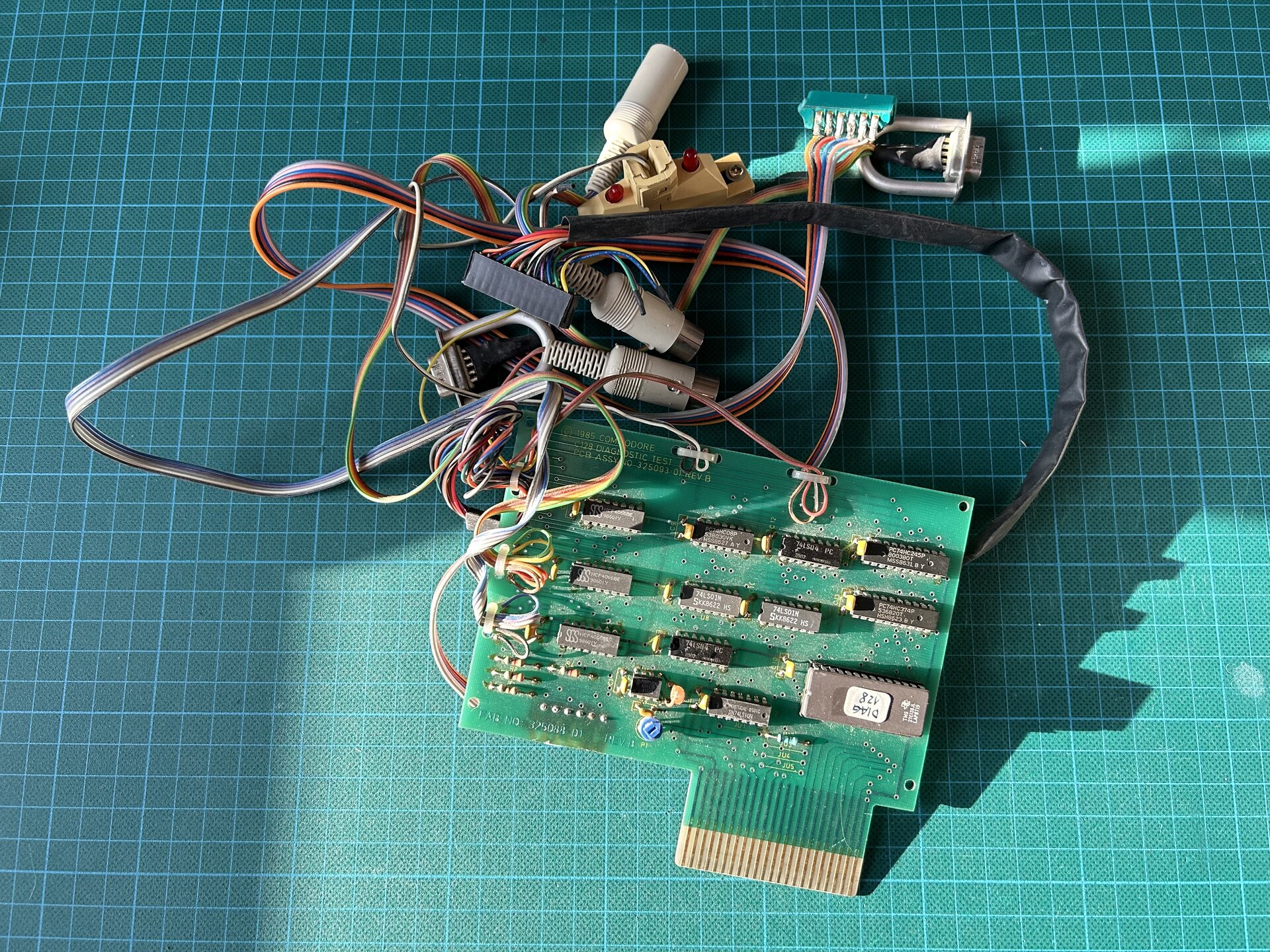
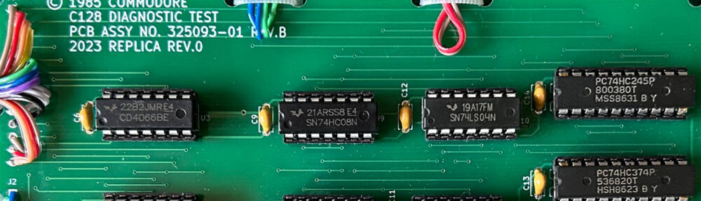
The C-128 Diagnostic Test cartridge that was donated
It was a “C-128 Diagnostic Rev 1.4” with harness “ASSY NO. 325093-01”, which I had never heard of before. Information on this cartridge seems sparse, but I found it mentioned on Jani’s page on diagnostic carts and in an older forum thread (German).
Originally, the tape port connector was soldered directly to the cartridge board. On my unit, however, some previous owner had tethered this connector to a wire like the others. Maybe because the connector pads were coming loose, or maybe to test a C128DCR, which is known to have its tape port in a different location.
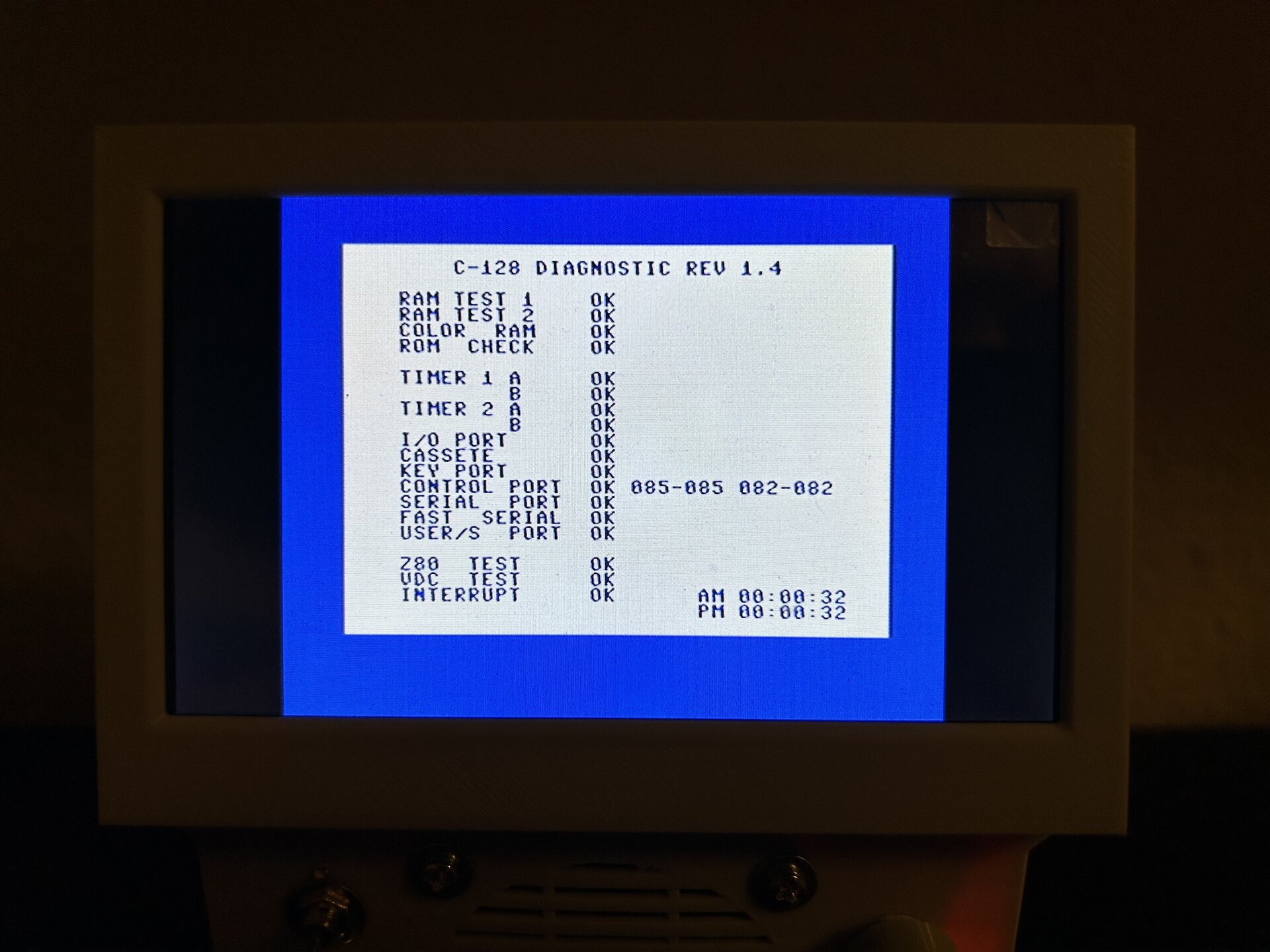
The C-128 Diagnostic Test cartridge at work
Anyway, after soldering a few loose wires, I tried the cartridge in a known-good Commodore 128. I was happy to find that it still worked fine! Next, I could have started repairing the other C128 motherboards mentioned above. But since this test cartridge seemed a bit uncommon, I decided to try to replicate it first. This seemed like an interesting and fun project, and like a great opportunity to try out a new feature in version 7 of KiCAD.
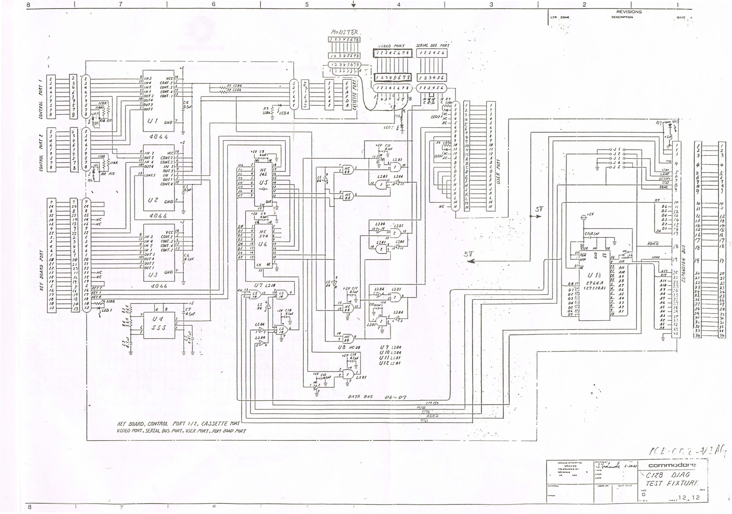
Original schematic of the diagnostic cartridge
I was able to obtain an almost readable version of the original schematic from Forum64. But I didn’t feel very confident to use just that for a couple of reasons. One is that it was easy to directly spot a difference between the schematic and the actual cartridge. There is a potentiometer on the PCB which is missing in the diagram.
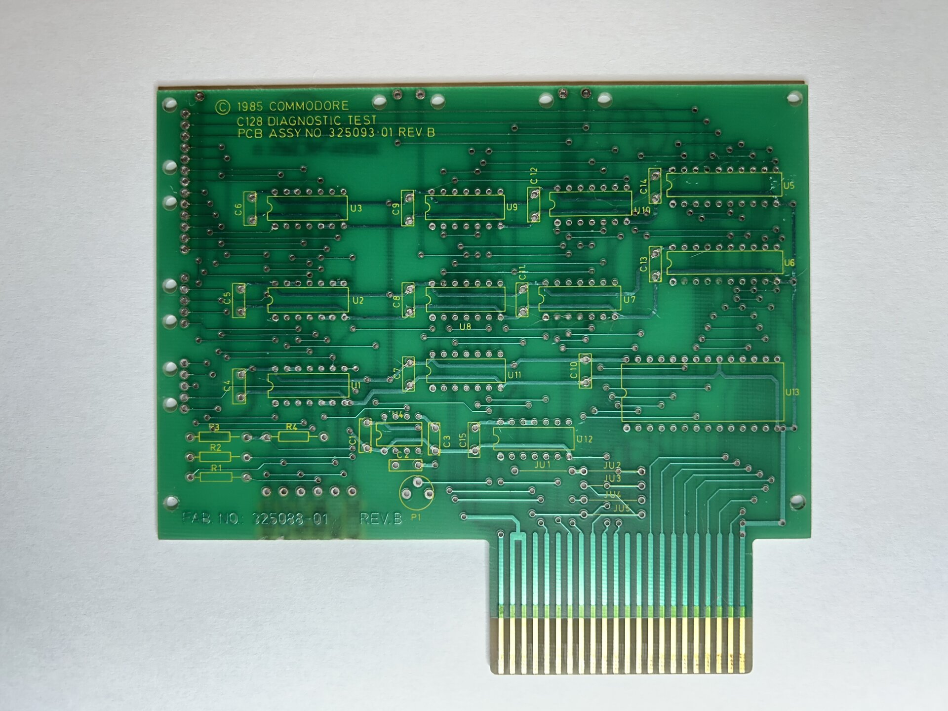 So I went one step further: I carefully desoldered all the components from the original cartridge to make high-quality scans of both its sides. I manually edited the resulting images, carefully aligned them, and finally imported them correctly scaled into the KiCAD PCB editor. Then I placed all the components so that they aligned with the pads on the images.
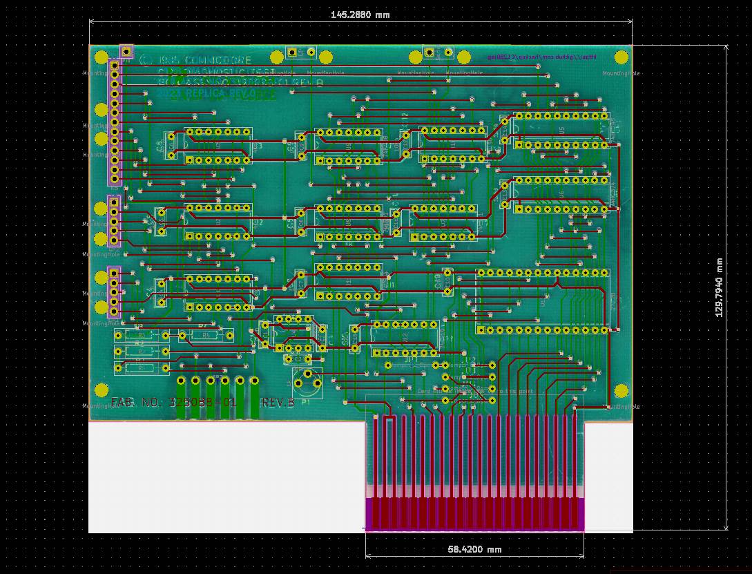 Finally, I carefully traced all connections and vias, always going back and forth in KiCAD between the PCB editor and the schematics. This was essentially the same process I had used to replicate the Pagefox cartridge some time ago.
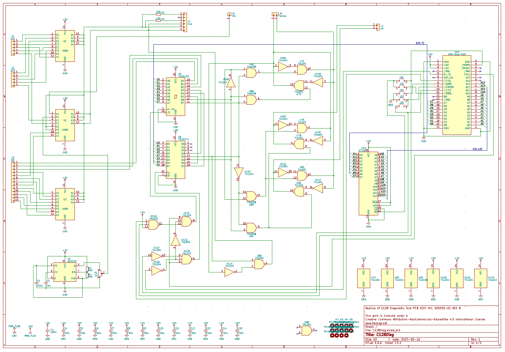
The schematic of the diagnostic cartridge reconstructed in KiCAD
Once I was confident that I had accounted for all connections and KiCAD’s checks assured me that my layout matched the reconstructed schematics, I was ready to order a small batch of PCBs. When they finally arrived, I immediately started assembling one of them. By far the hardest part was wiring all those connectors, but I was rewarded in the end: The replica worked just as well as the original!
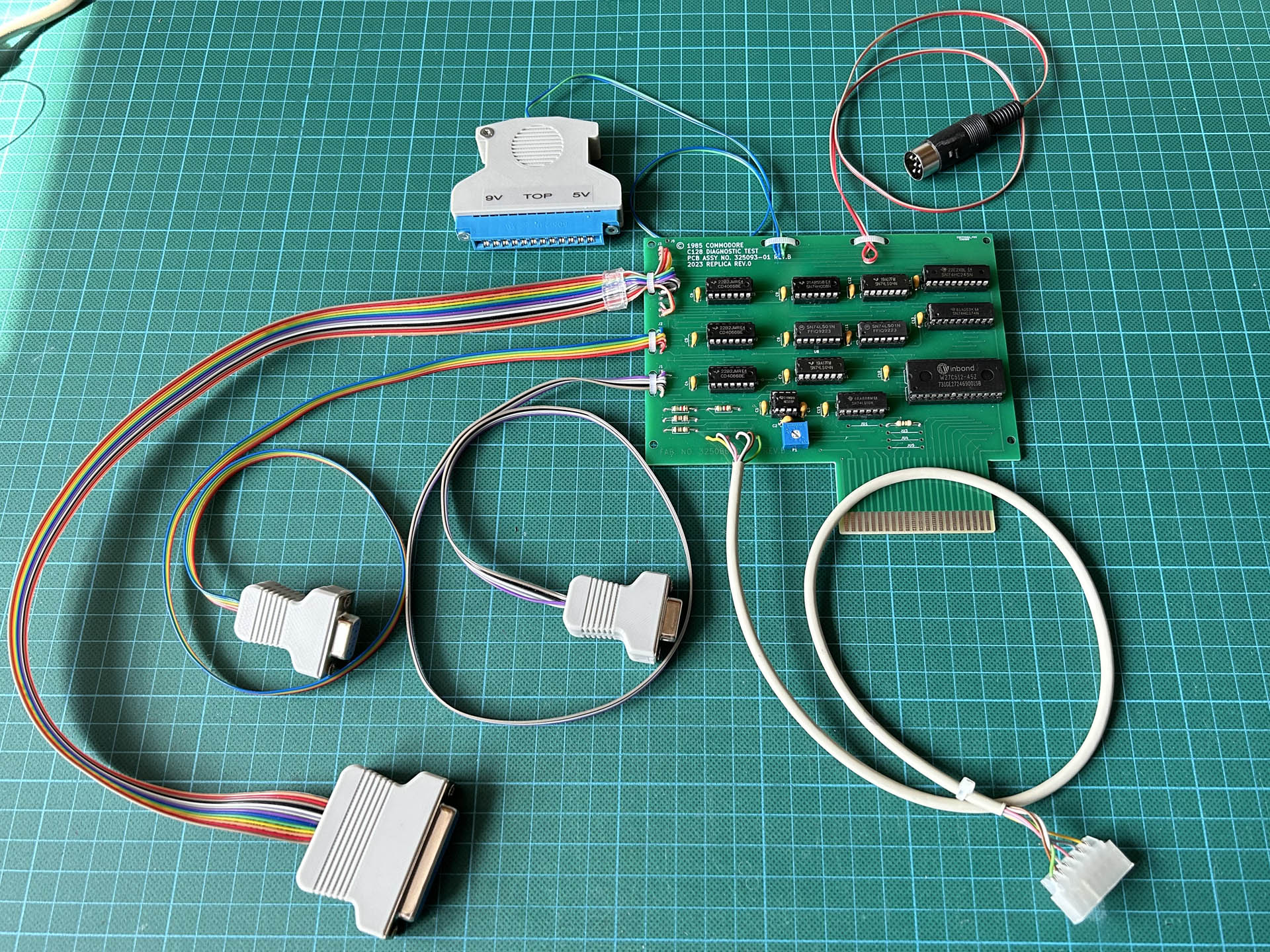
The finished replica with all its connectors
As usual, it will take me some time to tidy things up, and then I will release the sources for this project. At the moment I have too many projects running in parallel and not enough time for all of them. Also, I’m considering creating a new, more compact board layout for this cartridge, with lots of IDC and crimp connectors, which would make life a lot easier when building the test harness.
Update 2023-05-28
The models for the 3D-printed housings of the various connectors shown in the pictures are available on my Thingiverse and Printables pages.
Update 2023-09-03
I finally found the time to clean things up enough to release the sources for this project. I also added the wiring information for the test harness to the schematics, so if you are trying to build one yourself, this is where to look. All the necessary information is now available on my Github.
Also, rev.1 of the replica board can now be ordered directly from PCBWay.


Fantastic. I’ve been searching for one of these since I first found out about the C128 and 128D diagnostics. Unfortunately all I could find was some low res images and scans on an old forum, and that wasn’t enough to reverse engineer it.
Jani helped out by modifying one of the diagnostics to allow it to run without the harness, it works by skipping the port tests. So I’m glad you found one and have done the work to preserve it.
Do you plan on releasing the PCB design files? I would love to test it out and run the tests properly. Cheers
Thanks, Mark! Yes, I will definitely release the project sources including the PCB design files. It might take a few more weeks to make everything presentable, though. Also, I may need to add proper instructions on how to wire up all the connectors. Time is always too short.
Awesome! Yes of course there’s only so many hours in a day. Great work
Amazing! I’d love to figure out the connector part and how to get these connector hoods for the user and cassette ports. I didn’t see any reference in the Git repo.
You can find both user and cassette port connector caps among my designs on Thingiverse: https://www.thingiverse.com/hackup/designs
Hey there – I built one of these and with the 1.4 software, I can only get up to the I/O port test before it stops with a NG error. Any thoughts as to what it might be doing there? I’ve triple checked my circuit and harnesses and everything looks OK. And my C128 Neo has been working beautifully. I just want a diagnostic cart to troubleshoot as well. 🙂
Thanks again!
As for what exactly the test is doing at this point, I can’t tell you that either. The explanation in the diagnostics manual is “Cartridge slot I/O1, I/O2, HIROM”. That sounds to me like it doesn’t even involve the harness. Also, I don’t know enough about the C128 Neo to say whether it might be different enough from the original to explain this error.