A few years ago, when Xiaomi was making its Dafang WiFi camera, I bought two of them for a relatively low price. Since then, before every family vacation, I’ve set up one of them to spy on monitor our cat during the day before the cat sitter comes to take care of her in the evening.
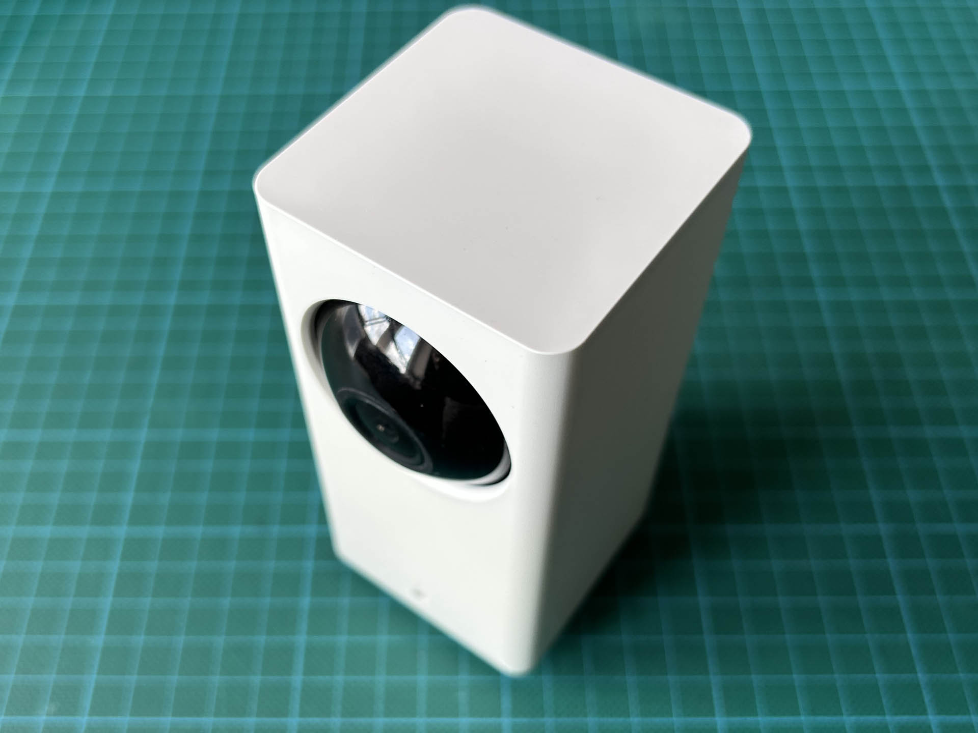
The Xiaomi Dagang wifi camera.
The main argument for this camera is, of course, the availability of a hacked firmware that disables any “cloud” access. This year I felt lucky and decided to upgrade to the open source u-boot bootloader first. I am still not sure what I did wrong, but I ended up with a bricked camera that no longer connected to my network. To fix this problem, “You will need to desolder your bootrom, reflash it and solder it back,” as the update instructions happily announce.
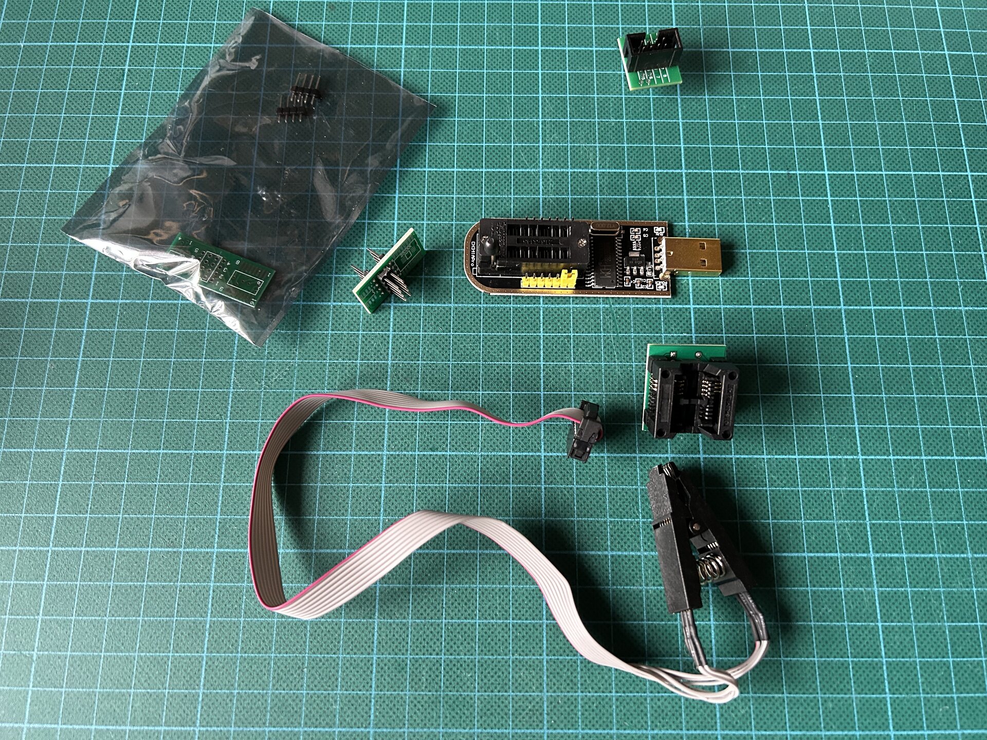
CH341a programmer kit.
So, I aimed my spare camera at the cat, ordered the recommended CH341a programmer module and some new GD25Q127CSIG flash ICs to be on the safe side, and went on vacation with my family. When we returned, the items had been delivered and it was time to repair the camera.
Disassembling the Camera
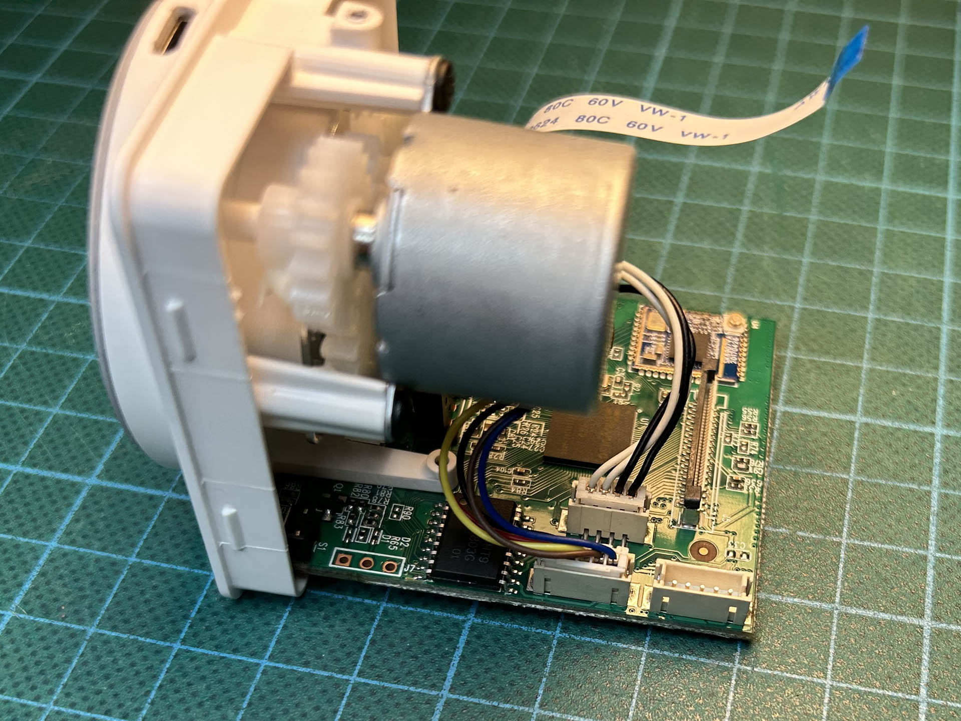
Disassembling the camera.
The first step was to disassemble the camera. This was actually pretty easy to do once I had found the two screws holding the back panel in place. Next, I used Kapton tape to protect the surrounding components and desoldered the flash chip using a hot air station.
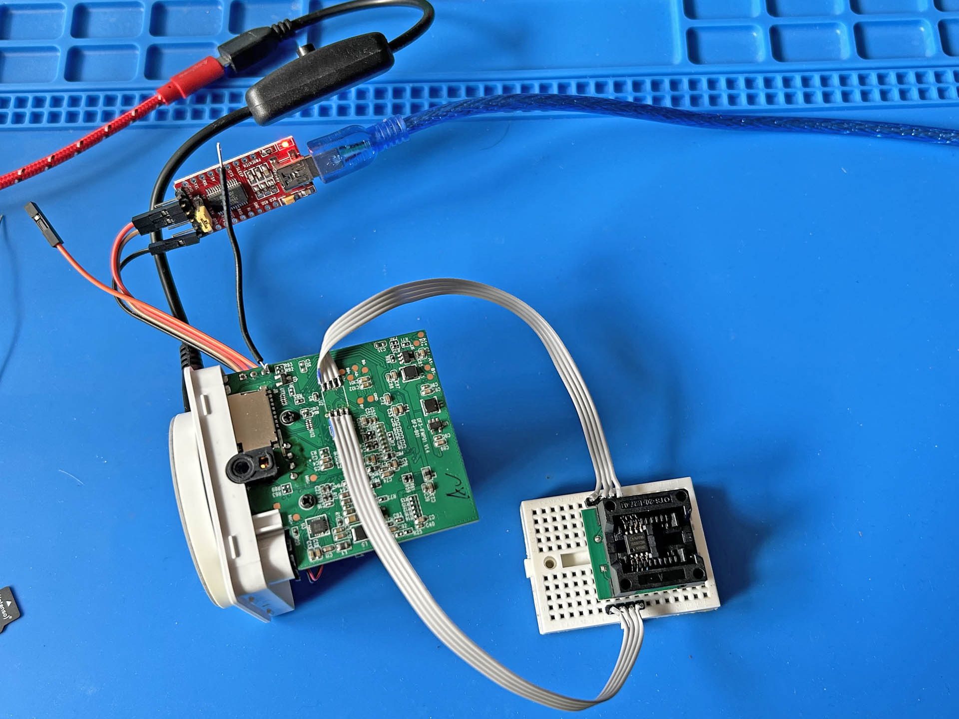
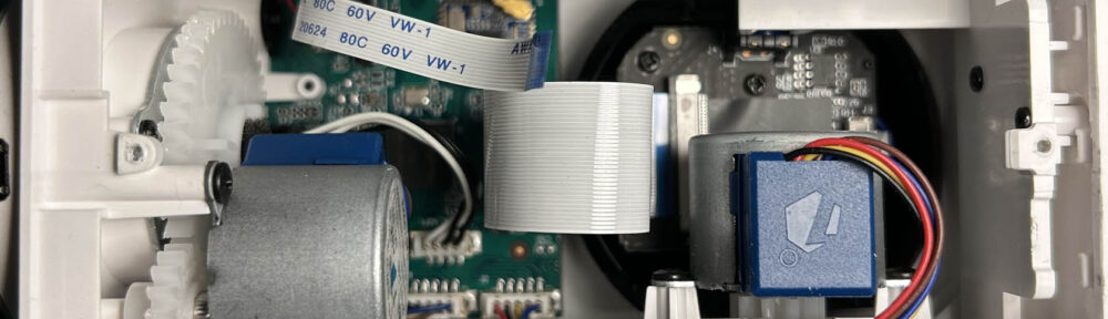
The flash IC desoldered and connected back to the camera temporarily, USB adapter connected to the serial console.
Expecting some trial-and-error, I came up with a temporary contraption that would allow me to easily switch the IC between the camera and the programmer. For the same reason, I also installed a pin header for the serial console.
As it turned out, both were well worth the trouble, because next I managed to make things worse by not following the exact recovery instructions. Instead, I tried to use the Windows-based NeoProgrammer (which I found in a tutorial for the CH341a) to flash the bootloader. I suppose this could have worked, but the way I did it, I ended up with an erased flash containing only u-boot in the wrong memory location.
Programming the Flash Memory
Things started to look better after I finally returned to the recovery instructions. I now followed them to the letter, used flashrom for programming, and was rewarded with u-boot booting and logging to the serial console!
git clone https://github.com/Dafang-Hacks/spiflasher.git
cd spiflasher/
cp -r uboot-fullhd.bin fullflash.bin
dd if=/dev/zero of=fullflash.bin bs=1 count=1 seek=16777215

flashrom -p ch341a_spi -V -c "GD25Q127C/GD25Q128C" --layout rom.layout --image boot -w fullflash.bin

# connect IC back to camera and USB adapter to serial console

picocom -b 115200 /dev/ttyUSB0
It would still not boot the Linux kernel, however, because I had managed to erase that from the flash along with everything else. Here is the expected flash memory layout:
00000000:0003ffff boot
00040000:0023ffff kernel
00240000:0058ffff roofs
00590000:0062ffff driver
00630000:00acffff appfs
00ad0000:00ccffff backupk
00cd0000:00d6ffff backupd
00d70000:00f6ffff backupa
00f70000:00faffff config
00fb0000:00feffff para
00ff0000:00ffffff flag
In the end, I was able to solve this problem by following the instructions on yet another “how to unbrick” page. It involved installing a version of the original firmware by copying it to the SD card and manually loading it using the serial console:
fatload mmc 0:1 0x80600000 demo.bin 0xa8ffc0 0x40
sf probe
sf update 0x80600000 0x40000 0xa90000
reset
After that was done, I could then flash the modified firmware again the “regular” way.
Final touches
At this point, the system was booting Linux again, and after I reconnected the camera daughter-board, it continued to boot and connect to my WiFi! Everything seemed to work fine now, except for the camera’s MAC address, which would change with each reboot.
This was due to the fact that the MAC address is read as a parameter from the “para” section of the flash memory. Fortunately, I had read and saved the entire contents of the flash when I first started the NeoProgrammer. So I extracted the “para” section (and the “config” section for good measure) from that file, saved them as separate .bin files to the SD card, logged into the camera via ssh, and flashed the contents back:
flash_eraseall /dev/mtd9
dd if=/system/sdcard/para.bin of=/dev/mtd9
flash_eraseall /dev/mtd8
dd if=/system/sdcard/config.bin of=/dev/mtd8
reboot
Finally, everything was back the way it should be! I removed my temporary contraption, soldered the flash IC back onto the board, and reassembled the camera.
In retrospect, I suspect that if I had followed the recovery instructions exactly in the first place, the camera would have been up and running again immediately. But where’s the fun without a little detour?


