Recently I had the opportunity to buy a Commodore SX-64 for a very reasonable price. Back when I had my Breadbox C64 as a kid, I was fascinated by this portable version and dreamed of owning one myself to take on our family vacations. In short, I couldn’t resist and bought it now.

My newly arrived SX-64.
When the SX-64 arrived, it was generally in working order. There were a few things to clean, repair and fix, but I’m not a collector, so that’s at least half the fun. The device came with an EPROM installed instead of the Kernal ROM, and a switch dangling from the front that allowed you to choose between the stock Kernal an JiffyDOS. That generally felt like a good idea, except that it only changed the Kernal of the C64, not the ROM on the floppy drive. And the dangling switch wasn’t very attractive either.
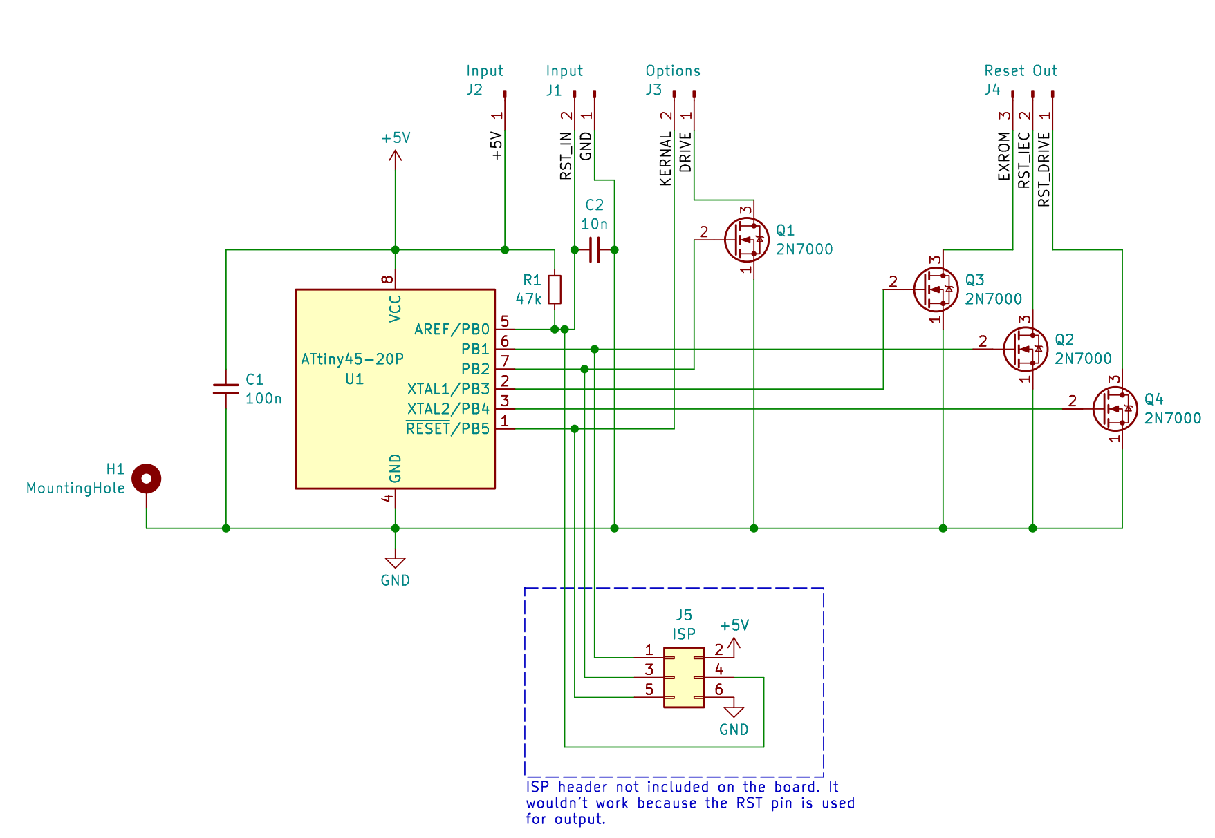
SX-64 Tiny Reset rev.1 schematics.
Of course, drilling a hole in the SX-64 was out of the question, so I was looking for an alternative. I knew about a project by some people on Forum64 to replace the CRT with a TFT, which included a new controller front panel that featured a circuit to solve this problem. There is also a device called the “SX-64 Ultra Reset” created by Jim Drew that would do what was needed here. I would have bought it immediately, but unfortunately when ordering from Europe, shipping, taxes, and import duties by far exceed the very reasonable price of this unit. (However, if you are in the US, you should definitely consider purchasing the SX-64 Ultra Reset!)
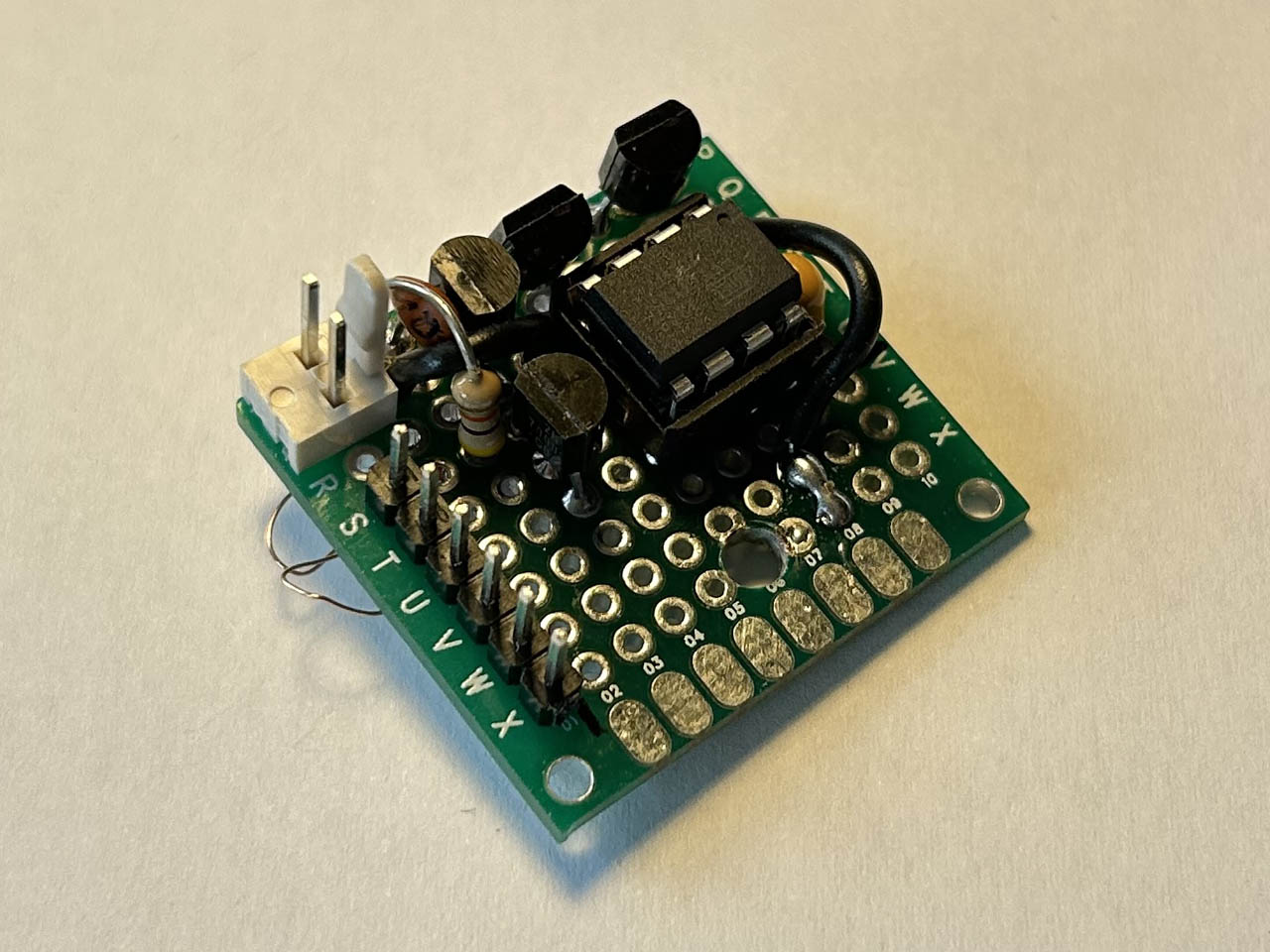
Perf board prototype for the tiny reset.
The SX-64 Tiny Reset
So once again I decided to do what is more fun anyway: I designed and built my own reset module, called the “SX-64 Tiny Reset”. It uses the drive reset button on the front panel of the SX-64 as its only input. The reset button connector is removed from the floppy controller board and simply connected to the reset module instead.
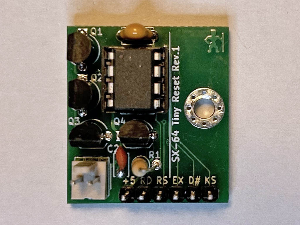
SX-64 Tiny Reset assembled on a printed PCB.
The ATtiny25 on the module counts the number of times the reset button is pressed. Depending on the number of short button presses, it triggers different actions:
| Clicks | Action |
| 1 | Reset the floppy drive. |
| 2 | Reset the SX-64. |
| 3 | Reset the SX-64 and hold EXROM for a short time to bypass reset protection. |
| 4 | Toggle internal drive device number between 8 and 9. |
| 5 | Toggle Kernal and/or floppy ROM. |
| 7 | Reset drive number and Kernal settings to default. |
Both the selected drive number and ROM bank are saved in the ATtiny’s internal EEPROM, so they are automatically restored even after the SX-64 was powered off.
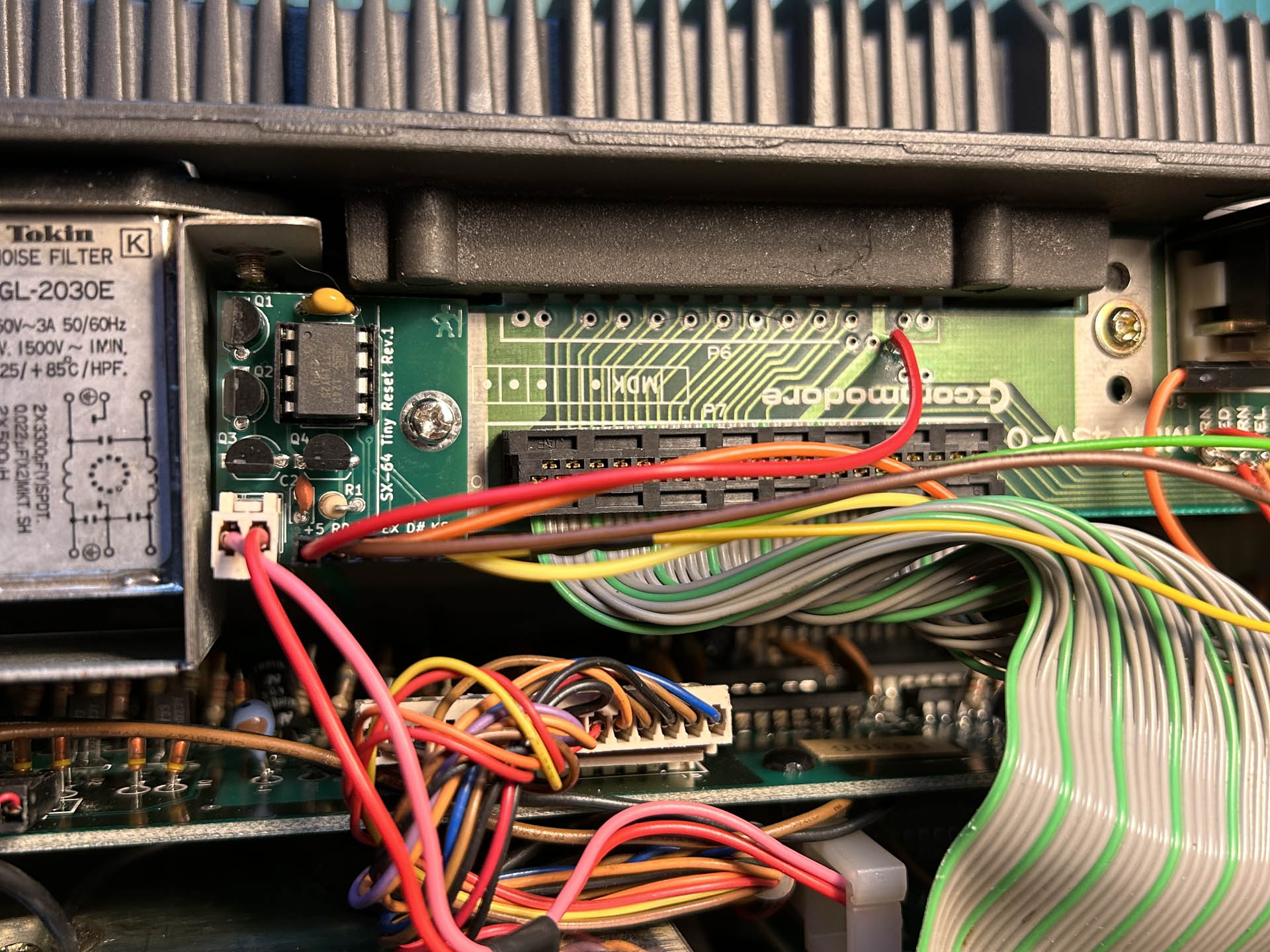
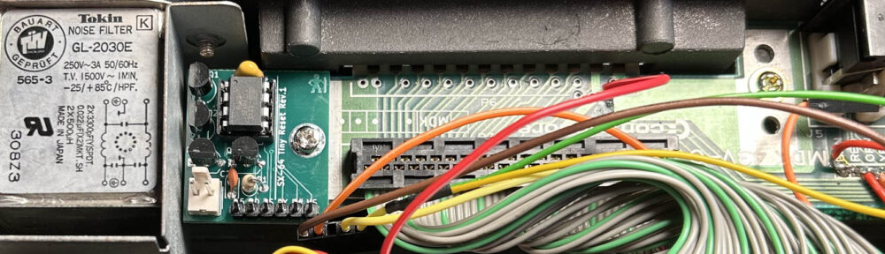
Rev.1 of the Tiny Reset module installed in my SX-64.
The part count for this project is not very high, so the board is assembled quickly. But it requires some care to wire it correctly to the various points inside the SX-64. Also, the ATtiny cannot be programmed via the ISP interface, because its reset pin is used as an additional output. An external programmer like the TL866 is needed for this.
Next, I need to sort and clean up the project files as usual, and I still need to decide on how exactly to publish and share them. So, look out for an update.


