The prototype batch of PCBs for revision 4 of the Pi1541io board didn’t take long to ship and it arrived from PCBWay while I was on vacation. Today, I finally managed to assemble one of the boards and everything seems to work great!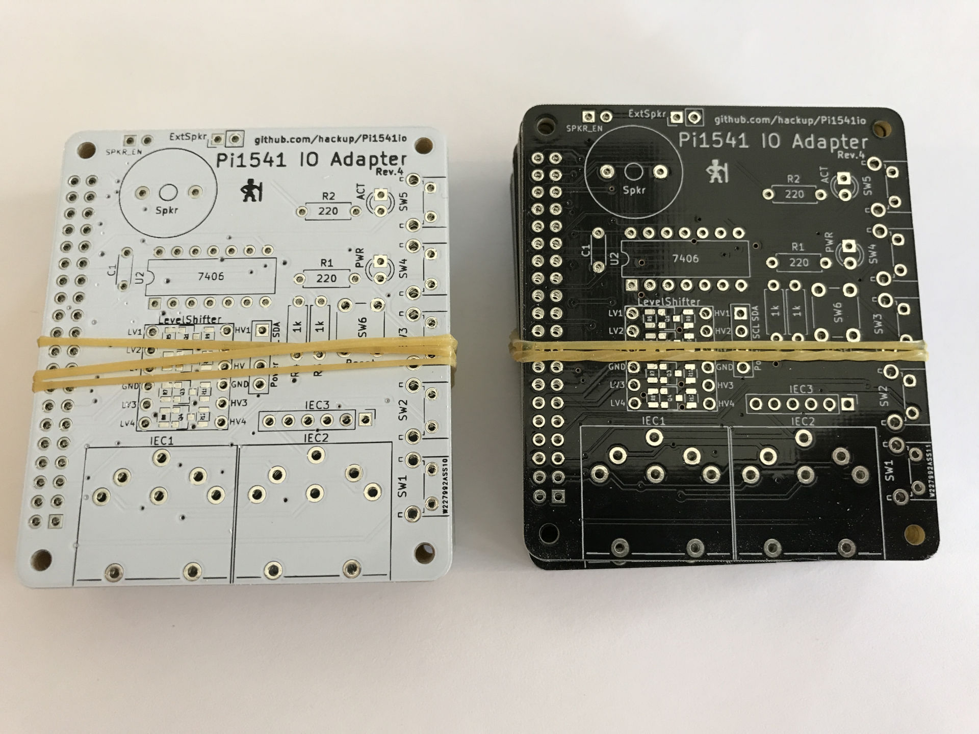 Revision 4 is basically what the previous one should have been: an improved rev.2 with an added I2C connector for an OLED display. In this revision though, the I2C connector can be configured to accommodate different kinds of display modules.
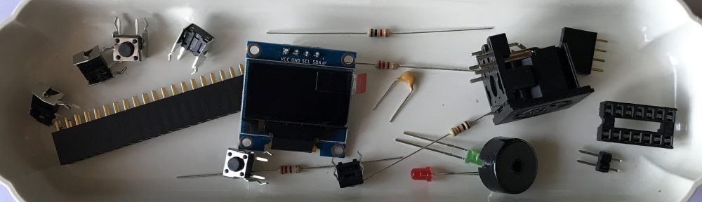
Again, the BOM for this board is mostly identical to that of revision 2. But I’d recommend you get yourself a compatible display, too.
| 1 | OLED Display with I2C SSD1306, 128x64px | eBay (China) eBay (Germany) | |
| 1 | J12 | 1×4 pin female header | eBay (China) eBay (Germany) |
When assembling the board, you need to make your choices and configure the solder bridges as described for revision 2. Additionally, you need to configure the I2C header using new solder bridges if you intend to use it.
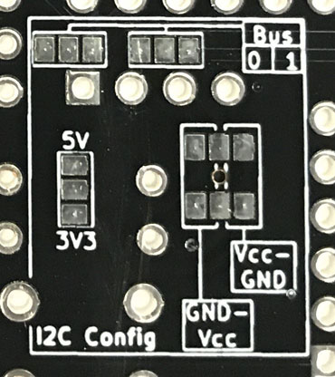
Configure the I2C header.
- Choose whether to power the display module with 5V or 3.3V. You must not use 5V if your display module is lacking its own voltage regulator! If in doubt, choose 3.3V — it should work in basically all cases.
- Configure the pin order for your display module. You need to choose between one of
GND-Vin-SCL-SDAorVin-GND-SCL-SDA. - If you configured your board to use the 7406 IC as a bus driver, you have the choice between using I2C bus 0 or 1 of the Raspberry Pi. If you opted for the “simple” layout without the 7406, you are limited to using I2C-0.
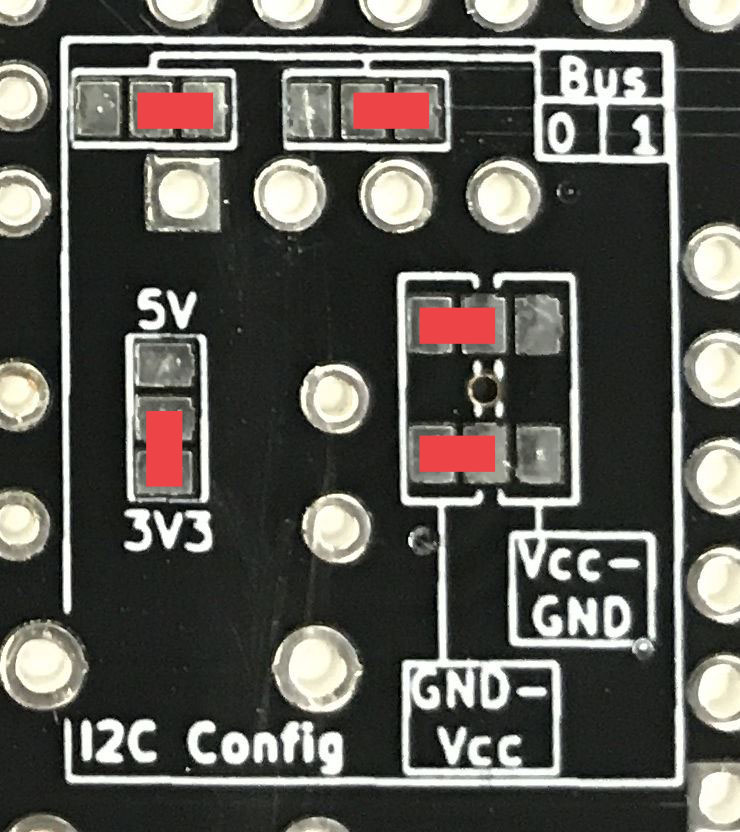
Example for a valid I2C configuration.
[Update] In the example image above, the I2C header is configured for 3.3V, I2C bus 1, and a display module with the pin order of GND-Vin-SCL-SDA.
 The project sources will again be available on Github as soon as I find the time to update the documentation. In the meantime, you can already order your boards on PCBWay, if you like.
Update: Sources and Gerber files for revision 4 are now available on Github.


@Tom Sorry I missed your question back then. The cathode of the LED goes onto the square pad. The markings of the default KiCAD LED footprint aren’t very helpful.
@vivvvi I haven’t tried a Pi Zero myself and I’m not sure I’ll be able to help you much from remote. Neither of the LEDs is required for the Pi1541 to function, that much I can tell you. Things you could try off the top of my head:
* Connect a monitor to the Pi and check the output.
* Enable the feature displaying activity on the IEC bus.
* Solder the second LED and see if it shows any reaction.
* Double-check your Pi config.
* Triple-check you soldering.
* Try to find people with Pi Zero experience on the Pi1541 thread on Lemon64.
Hi
Bought a kit pi1541 rev 4, display starts up with the drive og 1541 and then nothing happens on the I2C oled display.
then i added ignorereset = 1 , now display works fine but buttons doesnt work 🙁
what have I missed ?
Best Regards
Dennis
@Dennis, I had the same problem and then found out that I was missing a specific setting:
“If you build option B you will need to place the line “splitIECLines = 1″ in the options.txt file found in the root folder of the SD card.”
Had same problems with no OLED – you need the splitIECLines = 1 as stated by Christian
Hi, I bought this Rev 4 Pi1541 io hat and used it with a Raspberry Pi 2 (the pi1541 site has a working kernel for the Pi2); it worked well for a while but suddenly now I can’t mount .d64 images from the 1541 folder in the sdcard; it hangs out forever and when I hit Run/Stop + Restore it always throws the error “Device Not Present Error”
But it works in sd2iec mode, i.e., I’ve put a bunch of .PRG files inside 1541 folder and can load and run them with LOAD “gamewhatever”,8,1 and also I can list the dir by LOAD “$”,8.
Things I’ve tried:
configured the Pihat as device 8 and 9, no change
used a beefy 5V 3A power supply, no change
checked pi hat IO pins for continuity with digital multimeter, all passed
reformated sd card, re-copied kernel , config and option files, dos1541 rom, no change
changed serial cables (although they are known good because I can use a real 1541 without problems) and serial port order (i.e. C64->PiHAT->real 1541 and C64->real 1541->PiHat no change
I’m out of options, thank you
Hi
I bought the Rev4 Pi1541 hat and installed it on a RPi2 and it worked ok for a while; then it started to work only in IEC mode i.e. I can only load PRGs from the sdcard, including FB64 but everytime I try to load a .D64 image from sdcard (either via FB64 or by the physical buttons on the Pi1541 hat) I get a DEVICE NOT PRESENT ERROR.
I tried many things: settings the config options to drive 8/9, many different 1541 rom files (all from VICE emulator), reformatting sdcard, redownload all files from pi1541 site and checked connectivity ok with multimeter of every gpio pin in the RPi2.
What could be the cause of this problem? thanks in advance
@roberto First, sorry for my relayed reaction. Due to some WordPress issue, I didn’t get any notification mails for a while, so I missed your comments (among others). Second, I’m also sorry to hear of your problems with the Pi1541. Unfortunately, it is very difficult to debug such issues from afar. From your description, it sounds like a hardware issue to me. Maybe the level shifter, maybe the 7406 (depending on how your board was assembled), maybe just a bad solder joint. If you bought your Pi1541 IO Adapter as an assembled product I can only advise you to contact your vendor and as them for support.
Hi1, I’m trying to build the rev5, is there any hints i should follow? I need documentation for the back side where Jumper pads and SQR enable are present, Thanks a lot!
Stefano
Hi Stefano, For further information and instructions, please also refer to the posts on the previous revisions of the Pi1541io board. Concerning the jumper configuration, you’ll find the posts on rev.2 and rev.4 of the board most helpful, I think.
Hi
I want to use the bus driver i.c. but I’m not quite sure which pads to solder-jump. I find the labels on the board confusing when compared to the pads layout in the circuit. Can anyone help me check this?
The solder jumpers to select the bus driver IC are described at length in my post on rev.2 of the board.
I have same issue with roberto.
rev. 5 buttons not working
I built latest revision and connected it to a rpi 3A+
Option B i2c bus master 1
It boots, oled works and also on hdmi I got output
but I cannot control it with the soldered buttons or the keyboard
what I could have missed?
What were than plan for SRQ reserved box? It looks like 4 components, J9 jumper, and enable jumper.
Many years back, when I created my PCBs for the Pi1541 project, the firmware had no support for the “burst mode” which uses the SRQ signal to increase data transfer rates between a C128 and a 1571, for example. If I remember correctly, we were already discussing how such support could be added. So I took a guess at how the SRQ signal might need to be connected later on. That is what the reserved box is for.
Only a short while later, Steve changed his mind on how to distribute the firmware, it is no longer open now. Although I had already donated a considerable amount to Steve before, I didn’t have access to later versions of the firmware and so I lost interest in the project. I don’t know if support for the burst mode was ever implemented.
Thanks for a great design! I have a rev 4 board and wanted to add a rotary encoder. I took 5v and ground off of the 7406 and wired the other pins like this:
https://postimg.cc/fJLrLFW3
This seemed to be the easiest way to get the required pins without having to solder directly to the tightly-spaced GPIO header. Perhaps you can fit a 5-pin header for a rotary encoder on rev 6?
Thank you for your feedback, I appreciate it! Actually, support for the rotary encoder had been implemented in the firmware shortly after I finished rev5 and I had a connector planned for rev6. Unfortunately, it is unlikely that there will be a rev6 anytime soon for the reasons described in my previous comment.
Great little gadget. It took me a while to figure a few things out like why it wasn’t working to begin with. It helps to RTFM I suppose 😀. Anyway, it is working fine but I have a few minor issues.
1. When using a LCD display, it covers the reset button.
2. You can’t tell by the LEDs whether something is happening or not. The red LED is always on, the green one does nothing.
3. The little solder jumpers are a bit of a pain. I know physical jumpers and dip switches make things a little harder from a PCB design perspective but make it a lot easier to quickly re-configure something without having to break out the soldering iron.
On a side note and I guess that isn’t your problem but has to do with Pi1541 directly is that Jiffydos for example only works when reading from a .d64 image. I have a few .prg files in the root floppy folder for easy access and loading them takes forever. When I put them into a .d64 file, they load as expected with Jiffydos. I have never experienced that using SD2IEC solutions.
Are you sure your green LED isn’t soldered the wrong way around? It should indicate drive activity at least when in emulation mode, iirc.
I have experienced the same as Tom: the green LED does nothing. The speaker neither..
I use v5 boards, RPi 3B+, option ‘A’. I checked the connections with a multimeter, and proved to be good. Additionally, I uploaded a small test program to the uSD card just to probe the GPIO13 and 16, so even the RPi is working.
Anyway, thank you for being available the plans, appreciate it.
Update: I was investigated further and spotted in the version history of v1.24 Steve mentioned a buzzer problem fix. So, started to check previous versions of kernel, and found the v1.21 green LED and buzzer was working (in v1.22 they were working as well, but was not stable for me).
At Steve’s site I could not find a contact to inform him, only the Patreon page.
I have a couple of spare RPi 3A+ boards. Any point in seeing if they work with a 1541io Rev. 4 board?
If the RPi 3A+ boards are functional, I sure they will work with any revision of the 1541io board.