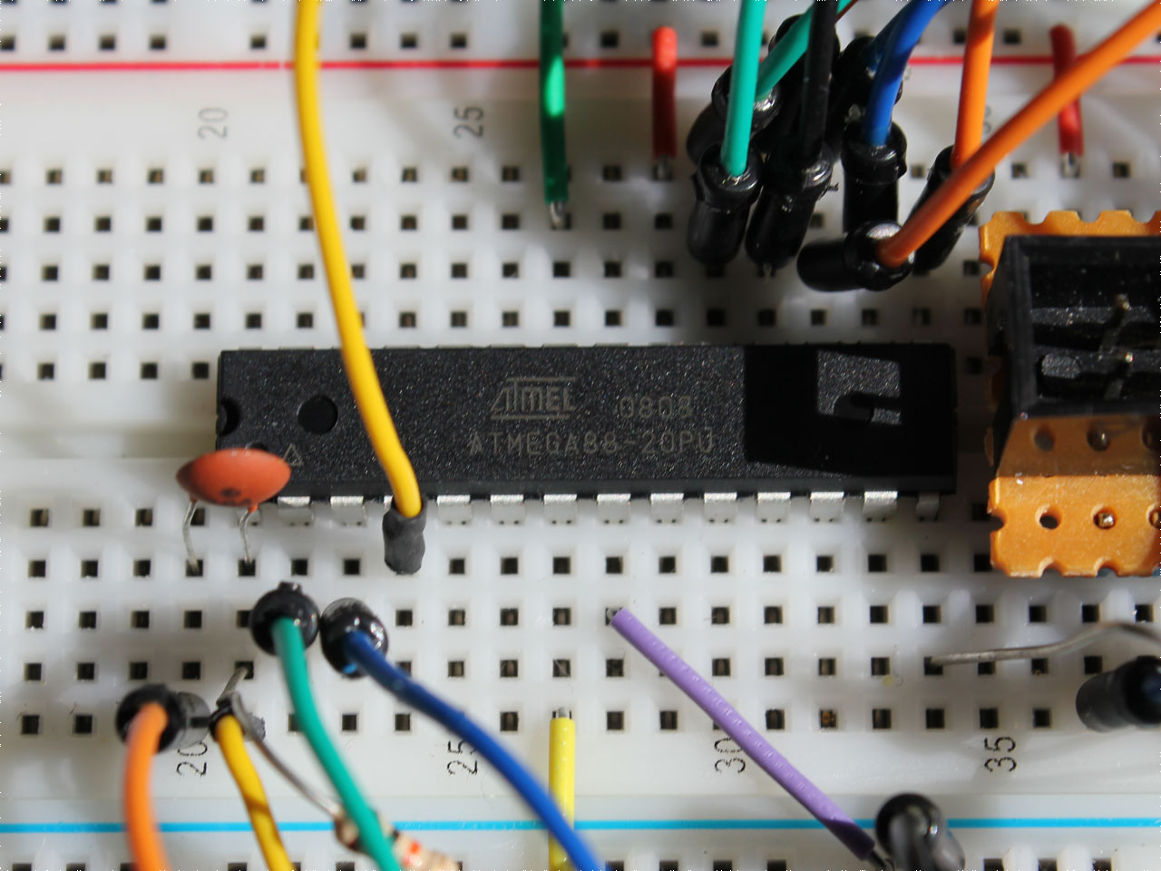
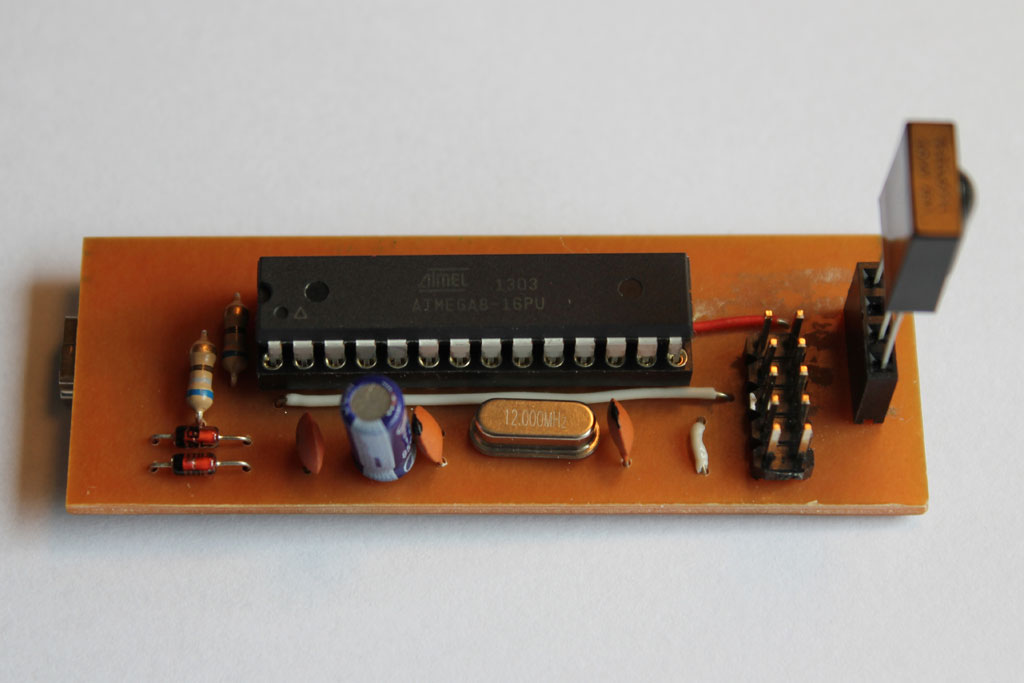
Android Development on Windows using an Intellibook Tablet

Earlier this year I acquired a 7 inch Intellibook Android tablet by ordering a trial subscription for a magazine on Java programming. When I tried to use it for Android development on Windows today, I couldn’t find a suitable USB driver. It took me a while to find out that the driver released by Google for their own devices would actually work.

Intellibook Tablet

Here is how to install it for the Intellibook tablet:

  1. Download the Google USB driver package for Windows.
  2. When finished, the driver is located in <android-sdk>\extras\google\usb_driver\, and you need to modify the file android_winusb.inf contained within. Add the following lines twice, once in each section [Google.NTx86] and [Google.NTamd64]:
    ;Intellibook
    %SingleAdbInterface%        = USB_Install, USB\VID_2207&PID_0010
    %CompositeAdbInterface%     = USB_Install, USB\VID_2207&PID_0010&MI_01
    
  3. Connect the tablet to the PC and install the modified driver.device_manager
  4. Create the file %USERPROFILE%\.android\adb_usb.ini containing the vendor code 0x2207 or add it if the file exists:
    echo 0x2207 >> "%USERPROFILE%\.android\adb_usb.ini"
    
  5. Remember to enable developer options and USB debugging on the device.

This worked for me, but of course there is no guarantee since Google does not support this device. On the other hand, it might also work for other “no-name” devices lacking suitable drivers. To find the hardware id string needed to modify the driver’s *.inf file connect the device to the PC, locate it in the Device Manager, and right-click to open properties -> details -> hardware-id. Try at your own risk…

Cheap USBASP Sticks for V-USB Development

A while ago I ordered a couple of cheap USBASP sticks. They are to be had on Ebay for as little as 2,50 € including world wide shipping and meant to be used for programming AVR microcontrollers. The programmer itself is based on an ATMega 8 controller so one of the sticks can actually be used to update the USBASP firmware on the other one. All it needs is shortening JP2 on the board to be flashed.

usbasp


avrdude -v -c usbasp -p atmega8 -U flash:w:usbasp.atmega8.2011-05-28.hex

But that is not even best part: the USBASP firmware is based on the open source V-USB driver, meaning these sticks can easily flashed with any other firmware using the same driver. So, they make for a cheap, complete, and easy to handle development platform for USB projects like the IR receiver introduced in an earlier post.

USB Receiver for the Ruwido Merlin IR Keyboard

When I noticed this compact IR Keyboard was on sale for no more than 1.- € I had no choice but to order a couple. One of them might prove useful when I manage to set up a media center based on a Raspberry Pi some day.

Ruwido Merlin Keyboard

Of course, this keyboard comes without a receiver. But how hard could it be to get it to work with LIRC? Very hard, as it turns out. Fortunately, I wasn’t the first one to encounter this problem. There is an open source decoder for this keyboard targeting AVR microcontrollers and I had just come up with the idea to combine it with the V-USB stack to create a USB receiver when I found out that someone else had already done just that.

The circuit was easily set up on a breadboard, but the firmware needed a few minor modifications to compile with recent versions of avr-gcc. When those were done and the firmware flashed, the operating system would still refuse to accept the circuit as a valid HID device. It took me quite a while to figure out that the author had made and committed some changes that seemingly broke the USB stack. When I reverted to an earlier version, the device worked fine. My clone of the repository is available on Github and its master branch now holds the still working version of the firmware.

Ruwido HIDUSB 1.0

Then I created a compact board to hold all the component. It has a single sided layout with only a few jumper wires on the top side and I used the toner transfer method for etching. The result did not turn out very pretty but it does the job. Unfortunately, in the first version of my design I missed R3 so the images on the gallery show a quick-fix for that problem. The board also features a 10 pin connector for the ISP since the firmware will probably still require more work. I added the revised EAGLE files to the repository.

OpenWRT and Scripting Languages, Part 1

The RGB wall light project is currently on hold due to a massive lack of time. Still, I’m taking little steps of preparation for the second phase of the project, the software intended to control the RGB matrix. I could use the gcc cross compiler for the job, but using a scripting language to develop directly on the device promises to be far more comfortable. I’d like to narrow this down to languages readily available as packages for OpenWRT which leaves me with Erlang, Lua, Ruby, Perl, and Python. Since I feel like trying something new I’m going to rule out Perl for now.

Make Room

The installation of the bleeding edge OpenWRT version called “Attitude Adjustment” on the TL-MR3220 leaves about 1MB of space for additional packages to be installed – which isn’t even close to being enough for this purpose. So, the first step is to extend that space and the currently recommended way to do this is to move the overlay mount to an external USB device: Continue reading

Fixing Broken PSU of Asus WL-500gP Router

I’ve been using the Asus WL-500g Premium under OpenWRT for years. I always keep a second cold-spare device in stock to minimize our household’s downtime in case the router breaks. Last year, it was actually the router’s power supply unit that ceased to function. After I replaced it with the PSU from the spare device everything was back to normal. The same thing happened again this week, so I decided to document how I fixed the wall-wart back then.

Note: This is potentially dangerous so don’t try this at home! You’ve been warned.

Actually, the hardest part was to open the PSU. Both parts of the case are glued together, so separating them will inevitably scar the case. After the case was open, the worn out capacitor that broke the unit was clearly visible. I just de-soldered the capacitor, replaced it with a new one, and closed the case using two strips of adhesive tape. Done.

Wifi Enabled RGB Matrix Wall Light, Part 1

Inspired by the so called Lampduino and several other related projects I decided to build my own version of a RGB matrix wall light some time ago. During the last few weeks I finally managed to start out on this project.

Hardware

The matrix of 64 individual cells and the LED back-plane are made from 4mm thin plywood that I spray-painted with a silvery varnish. The outer frame is made from a stronger 14mm birch multiplex board, yielding a very solid construction. I also bought some thin, white PVC board intended as the material for the front cover, but I still have to figure out how to cut that nicely.

Lacking the ambition to create my own LED driver board I settled for the “Rainbowduino”, an Arduino compatible board developed and sold by Seeed Studio. In addition to that, I wanted the matrix to be controlled and programmed over the air. One of the cheapest, easiest, and most versatile ways to accomplish this was to modify an OpenWRT based router for this purpose.

Continue reading

Serial Communication Between an Arduino and the TL-MR3220 Router

Last time, I installed OpenWRT on the TL-MR3220 router and added a connector for it’s serial interface. Today, I wanted to try and connect this interface to an Arduino to make the two communicate. The router’s interface operates at 3.3V while the Arduino’s UART operates at 5V, so we need to convert between those levels. The cheapest way to do this that I could find is described here. It involves using a 74LS04 hex inverter chip to convert the 3.3V signal up to 5V and two resistors for a simple voltage divider to convert the 5V signal down to 3.3V.

Continue reading

OpenWRT and the Serial Console of the TL-MR3220 Router

The TP-LINK router TL-MR3220 is a very cheap (around €22 in Germany) yet feature-rich wireless 802.11n router that supports the open source OpenWRT firmware. It offers a USB port, allowing a bunch of additional peripheral hardware to be connected. Installing the matching OpenWRT nightly build was easy enough, the original firmware offers to do so using the standard web interface.

I was thinking about connecting one of them to an Arduino in a project to come. The integrated serial interface seems to be the obvious way to achieve this. The router’s board readily exposes the interface, so I added a 4-pin header to do a few tests. The pin-out of the interface is documented in the OpenWRT wiki. Using a standard FTDI adapter I then got access to the router’s serial console. From here it should not be to hard to use the same interface to connect to an Arduino instead.

Seeeduino Stalker: Writing to the SD Card

After I managed to upload the first sketches to the Seeeduino Stalker last week, I was eager to try the special features offered by this special kind of Arduino platform. I decided to try writing to an SD card first and followed the example included in the Stalker’s documentation. Which turned out to not work at all.

A couple of hours later and looking for errors in all the wrong places, I finally managed to find out how to use the FileLogger library:

  1. The SD card needs to be FAT16 formatted.
  2. The file that the the Arduino is writing to must exist 615-544-6598 , the library does not create files.
  3. The file must not be empty, it must contain at least one byte of data.

If these conditions are met, the following tiny sketch will work just fine and append data to the file:

#include "FileLogger.h"

void setup(void)
{
 byte buffer[] = "Hello World!";
 FileLogger::append("data.txt", buffer, 12);
}

void loop(void) {}

Update 10/8/12: Please note that this example will work with version 1.0 of the Stalker, only. For newer versions of the board you should try sadfatlib.

Connecting to the Seeeduino Stalker

A few weeks ago, Seeed Studio were celebrating their anniversary with a bunch of limited offers. Among other things, I acquired a pair of Seeeduino Stalkers v1.0 with an Atmega 168. Unfortunately, the serial interface on those boards is not labeled. So it took me a while to figure out how to connect the FTDI breakout board. With a small adapter board, programming the Stalkers with the Arduino IDE now works like a charm. (Select board type “Duemilanove w/ 168”.)