OpenWRT and the Zsun Card Reader

During the last few weeks since my first post about the Zsun WiFi Card Reader I learned a few things that I haven’t documented yet.

After I was able to confirm that my device has indeed PCB v2 but that flashing should work just the same, I tried the simple method described here:

  1. Insert a FAT formatted micro SD card into the reader and plug the reader into a PC (running Windows, in my case). The card should be assigned a drive letter, say “J:”.
  2. Connect to the WiFi access point created by the reader.
  3. Open http://10.168.168.1:8080/goform/Setcardworkmode?workmode=0
  4. Open the drive/card in the file explorer, create a new folder named “.update.” and copy the SD100-openwrt.tar.gz archive into it.
  5. Open http://10.168.168.1:8080/goform/upFirmWare – this should return status code “2”.
  6. Wait patiently for the described LED flashes!
  7. Connect to the new access point called “OpenWRT”.
  8. Open https://192.168.1.1/cgi-bin/luci and configure OpenWRT.

This worked like a charm (a big thanks to Warsaw!), but only 5 minutes later I managed to lock myself out with a bad WiFi config. Great. So I went ahead and soldered leads to the serial headers. But while I was able to receive and read the console output just fine I had no success sending any input to that console. Only today I learned that PCB version 2 is missing a jumper that needs to be connected in order to enable serial RX. Connecting this jumper has exceeded my meager soldering skills so far, though.

Fortunately, I learned another fact from a helpful comment on my previous post: By inserting or removing the SD card during boot, OpenWRT can be put into fail-safe mode that will reset the configuration. I kept inserting and removing it in quick succession for about 10 seconds in order to get the timing right. Now I’m able to connect to the WiFi again!

Update:
One of the images is showing an Ethernet cable attached directly to the board. This did not work for me and trying it was somewhat naive. It’s been brought to my attention that this might damage the SoC, too. If resetting an OpenWRT installation as described above is not enough, the best way to un-brick the device seems to be through the serial console as described in the comments.


The Zsun WiFi Card Reader

I’m not sure where I read first about the $8 Zsun WiFi Card Reader and the attempts by the people at Warsaw Hackerspace to flash it with their port of OpenWRT. It made me curious, so I went ahead and ordered a sample. Shipping from China took a while but I received the tiny gadget yesterday.

So far I could confirm the documented root access to the stock firmware via telnet on port 11880 using the password “zsun1188”. I have not tried flashing OpenWRT yet as I am not sure which of the at least two different PCB versions I got. Could anyone give me a hint on this?

The Fancy Lantern Stick

I’m not sure about other parts of the world, but back here in Germany we’ve got a tradition called Laternelaufen. It involves lanterns, preferably home-made from cardboard and colored paper, lantern sticks, and a bunch of happily singing children. And of course, it requires a way of lighting the lanterns. Traditionally, this is accomplished by the use of burning candles which are cheap and actually looking great, but will also ever so often result in the lanterns themselves catching fire. So, for many years there have been battery powered lantern sticks featuring a small light bulb on the upper end.

My daughter is very much looking forward to this year’s Laternelaufen events. What a great excuse for myself to get started on a small new project, the Fancy Lantern Stick! Here’s the list of major ingredients:

  • 20cm of PVC tubing 40mm in diameter, normally used for in-house plumbing
  • 50cm aluminum pipe, 6mm in diameter
  • 1 small piece of wooden board, roughly 15mm strong
  • Acrylic spray paint, the colors of your choice
  • Clear lacquer spray
  • 1 Arduino Pro Mini
  • 1 5V Step-up power converter
  • 1 Battery holder for 2 AA sized batteries
  • 8 WS2812B LEDs on separate tiny boards
  • 1 Switch
  • 1 Push-button
  • An assortment of wires, headers and connectors
  • Hot glue

When switched on, the Arduino will produce yellowish-white light from the 8 LEDs and simulate the moderate flickering of a candle flame. The red push-button on the handle triggers special light effects to show off.

The source code for the Arduino sketch is available on Github, and I’ll try to add a couple of photos showing the finished stick once I find the time and manage to borrow it back from my daughter.

Update:

I did manage to take a few photos of the finished stick today and added them to the gallery. Also, if there is enough interest I could supply more detailed information on how to build one of these, of course.


Wireless Sensor Network, Part 2

Still trying to save my batteries

By now it is time for at least an intermediate update on this project. In the meantime I have indeed revised the sensor boards by adding a switching transistor controlled through one of the remaining digital pins on the ATmega. The firmware was modified, and it will now power down the attached sensors before entering sleep mode. Disappointingly, this resulted in a battery lifetime extended by no more than roughly 10%.

On a mostly unrelated note, the voltage graph now looks “stepped” when compared to the previous one. This seemed to be a direct result of switching from maniacbug’s original driver for the RF24 module to the one newly optimized by tmrh20. I’ve got absolutely no clue why this would affect the voltage measurement against the bandgap reference, but there it was. If you can shed some light on this, please leave me a comment.

The next thing I tried, somewhat desperately, was to reduce the number of data samples by increasing the sleep time from 1 minute to 5 minutes. This had no discernible effect on battery life-time. But at least it leads to the conclusion that I need to further investigate power consumption during sleep mode.

So, just assuming that it was the sensors that were draining the batteries in sleep mode turned out to be a bad idea. Now I really need to replace my crappy 7€ multimeter with something a little more precise that will allow me to actually measure which part of the circuit is drawing which amount of current.

Wireless Sensor Network, Part 1

With all components finally having arrived from China, I built the first couple of wireless sensors a few months ago. They are using the cheap nRF24L01 transceiver modules for data transmission based on the RF24Network network layer. I’m using a Raspberry Pi with the transceiver module directly connected to its GPIO pins as the root node. The sensor nodes are controlled by an ATmega328 microcrontroller flashed with the Arduino firmware for convenience.

Each sensor node currently features a DHT11 humidity sensor, a DS18B20 digital thermometer, a BMP180 barometric pressures sensor and it’s powered by three AA cells. The controller spends most of its time in power-saving sleep mode, waking up to send a data packet about every minute. Each packet contains the readings from the three sensors as well as the battery voltage as determined against the bandgap reference.

The setup is far from final. For one, I’m still not sure how to store the data. Currently, it is just logged into a text file with an occasional and experimental import into OpenTSDB. I haven’t really come to trust OpenTSDB since I haven’t found a suitable and convincing way to backup the HBase data, yet.  Also, I might still replace the Raspberry Pi root node with an Arduino based MQTT relay.

First though, the power consumption of the sensor nodes needs improving. When I started out I was hoping for each node to run for close to a year on a single set of batteries. As you can see in the graph above, with the current design a set of three NiMH batteries with low self discharge lasts for no more than 6 weeks. What comes to mind in order to improve this, is to switch off the sensors and the transceiver in between samples. That is probably what I’ll try next. Please let me know if you’ve got any other ideas!


Minimal Arduino using an ATmega88

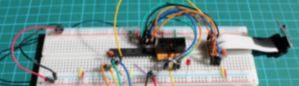
In preparation of the quest to build my own wireless sensor network I spent some time in getting a minimal Arduino up and running based on the ATmega8 chip. It was not before I finally succeeded that I realized it would be of no use in this case, because the ATmega8 lacks the ability to trigger an interrupt handler through its watchdog timer. So, I wouldn’t be able to use its power down sleep mode.

ATmega88 using internal clock

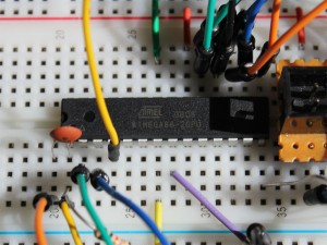
I then found a couple of ATmega88 chips in my stockpile, which aren’t subject to this limitation. Fortunately, setting this one up as a minimal Arduino turned out to be much the same. I mostly followed an existing guide, but added the Optiboot bootloader to the mix.

I first needed to compile the bootloader for the use with the internal osciallator at 8Mhz. So I added the following lines to arduino-1.0.5-r2/hardware/arduino/bootloaders/optiboot/Makefile:

atmega88_8: TARGET = atmega88
atmega88_8: MCU_TARGET = atmega88
atmega88_8: CFLAGS += '-DLED_START_FLASHES=3' '-DBAUD_RATE=19200'
atmega88_8: AVR_FREQ = 8000000L
atmega88_8: LDSECTIONS  = -Wl,--section-start=.text=0x1e00 -Wl,--section-start=.version=0x1ffe
atmega88_8: $(PROGRAM)_atmega88_8.hex
atmega88_8: $(PROGRAM)_atmega88_8.lst

I limited the baud rate to 19200 as greater values turned out to be less reliable in my setup. For this to work, I had to explicitly disable SOFT_UART in optiboot.c:

/* Switch in soft UART for hard baud rates */
#if (F_CPU/BAUD_RATE) > 280 // > 57600 for 16MHz
#ifndef SOFT_UART
//#define SOFT_UART
#endif
#endif

With that you can build the bootloader by running make atmega88_8 or omake.bat atmega88_8 on Windows in that same directory.

Next, I added the new Arduino type to arduino-1.0.5-r2/hardware/arduino/boards.txt. It should have been possible to add the board definition to a boards.txt file below the sketchbook directory but that did not work for me and the current version of my Arduino IDE.

atmega88_8.name=ATmega88 Optiboot (8MHz internal OSC)
atmega88_8.upload.protocol=arduino
atmega88_8.upload.maximum_size=7680
atmega88_8.upload.speed=19200
atmega88_8.bootloader.low_fuses=0xe2
atmega88_8.bootloader.high_fuses=0xdf
atmega88_8.bootloader.extended_fuses=0x00
atmega88_8.bootloader.path=optiboot
atmega88_8.bootloader.file=optiboot_atmega88_8.hex
atmega88_8.bootloader.unlock_bits=0x3F
atmega88_8.bootloader.lock_bits=0x0F
atmega88_8.build.mcu=atmega88
atmega88_8.build.f_cpu=8000000L
atmega88_8.build.core=arduino
atmega88_8.build.variant=standard

Finally, with the ISP connected, I installed the new bootloader using the Aduino IDE and can now upload sketched through the serial connection.

There seems to be one annoying issue left though. When the compiled sketch size is getting close to the limit of 7680 bytes the upload will fail with an error message. If anyone can shed some light on what I might have missed here, please leave me a comment.

OpenWRT and Scripting Languages, Part 1

The RGB wall light project is currently on hold due to a massive lack of time. Still, I’m taking little steps of preparation for the second phase of the project, the software intended to control the RGB matrix. I could use the gcc cross compiler for the job, but using a scripting language to develop directly on the device promises to be far more comfortable. I’d like to narrow this down to languages readily available as packages for OpenWRT which leaves me with Erlang, Lua, Ruby, Perl, and Python. Since I feel like trying something new I’m going to rule out Perl for now.

Make Room

The installation of the bleeding edge OpenWRT version called “Attitude Adjustment” on the TL-MR3220 leaves about 1MB of space for additional packages to be installed – which isn’t even close to being enough for this purpose. So, the first step is to extend that space and the currently recommended way to do this is to move the overlay mount to an external USB device: Continue reading

Fixing Broken PSU of Asus WL-500gP Router

I’ve been using the Asus WL-500g Premium under OpenWRT for years. I always keep a second cold-spare device in stock to minimize our household’s downtime in case the router breaks. Last year, it was actually the router’s power supply unit that ceased to function. After I replaced it with the PSU from the spare device everything was back to normal. The same thing happened again this week, so I decided to document how I fixed the wall-wart back then.

Note: This is potentially dangerous so don’t try this at home! You’ve been warned.

Actually, the hardest part was to open the PSU. Both parts of the case are glued together, so separating them will inevitably scar the case. After the case was open, the worn out capacitor that broke the unit was clearly visible. I just de-soldered the capacitor, replaced it with a new one, and closed the case using two strips of adhesive tape. Done.

Wifi Enabled RGB Matrix Wall Light, Part 1

Inspired by the so called Lampduino and several other related projects I decided to build my own version of a RGB matrix wall light some time ago. During the last few weeks I finally managed to start out on this project.

Hardware

The matrix of 64 individual cells and the LED back-plane are made from 4mm thin plywood that I spray-painted with a silvery varnish. The outer frame is made from a stronger 14mm birch multiplex board, yielding a very solid construction. I also bought some thin, white PVC board intended as the material for the front cover, but I still have to figure out how to cut that nicely.

Lacking the ambition to create my own LED driver board I settled for the “Rainbowduino”, an Arduino compatible board developed and sold by Seeed Studio. In addition to that, I wanted the matrix to be controlled and programmed over the air. One of the cheapest, easiest, and most versatile ways to accomplish this was to modify an OpenWRT based router for this purpose.

Continue reading