I’m not sure about other parts of the world, but back here in Germany we’ve got a tradition called Laternelaufen. It involves lanterns, preferably home-made from cardboard and colored paper, lantern sticks, and a bunch of happily singing children. And of course, it requires a way of lighting the lanterns. Traditionally, this is accomplished by the use of burning candles which are cheap and actually looking great, but will also ever so often result in the lanterns themselves catching fire. So, for many years there have been battery powered lantern sticks featuring a small light bulb on the upper end.
My daughter is very much looking forward to this year’s Laternelaufen events. What a great excuse for myself to get started on a small new project, the Fancy Lantern Stick! Here’s the list of major ingredients:
- 20cm of PVC tubing 40mm in diameter, normally used for in-house plumbing
- 50cm aluminum pipe, 6mm in diameter
- 1 small piece of wooden board, roughly 15mm strong
- Acrylic spray paint, the colors of your choice
- Clear lacquer spray
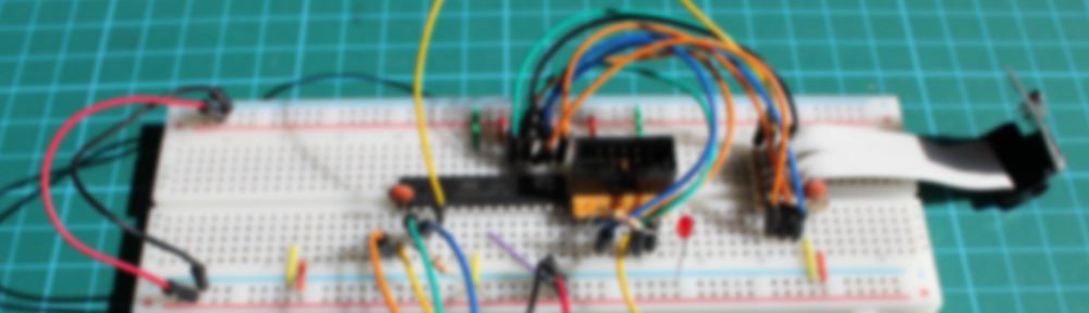
- 1 Arduino Pro Mini
- 1 5V Step-up power converter
- 1 Battery holder for 2 AA sized batteries
- 8 WS2812B LEDs on separate tiny boards
- 1 Switch
- 1 Push-button
- An assortment of wires, headers and connectors
- Hot glue
When switched on, the Arduino will produce yellowish-white light from the 8 LEDs and simulate the moderate flickering of a candle flame. The red push-button on the handle triggers special light effects to show off.
The source code for the Arduino sketch is available on Github, and I’ll try to add a couple of photos showing the finished stick once I find the time and manage to borrow it back from my daughter.
Update:
I did manage to take a few photos of the finished stick today and added them to the gallery. Also, if there is enough interest I could supply more detailed information on how to build one of these, of course.