TapecartFlasher Nano

In my previous post I introduced the Tapecart, a thumb drive for the Commodore 64, and built one of those. The only major issue with these great devices is the 1.5 hours it takes for the C64 to transfer the 2 MB of data to them.

Fortunately, Detlef Gerhardt came up with the idea of hooking up the Tapecart to an Arduino in order to transfer the data using a modern PC. It turns out, this speeds up the transfer considerably and it also eliminates the need for copying TCRT images using a SD2IEC or similar device. An early version of Detlef’s TapecartFlasher software is available on Github.

Tapecart and the Arduino. Ignore all the other components for now.

The original setup for the TapecartFlasher is as simple as it gets: simply hook up 5V and GND from the Arduino, then connect the 4 remaining lines of the cassette port interface to D2-D5. I tried this on a breadboard first and it worked out of the box! The most complicated part here was the lack of a proper connector, so I just soldered leads to the Tapecart module. Continue reading

The Tapecart – A Thumb Drive for the C64

The Tapecart is a relatively new piece of hardware that was devised for the Commodore 64 by Unseen and enthusi  and introduced in late 2016. The general idea is quite compelling: The small module features 2 MB of serial flash memory and plugs into the cassette port of the Commodore. By just entering LOAD or the “Shift+Run/Stop” shortcut, a small bootstrap program is run that will then very quickly load up to 64 KB from the Tapecart into the C64 for execution. No cable and no external power supply is required and important other ports remain unused. This is probably as close to a “thumb drive” for the old hardware as it gets.

Both the software and the hardware of the Tapecart are available under an open source license. The hardware is very cost optimized and can be built for only a few € or $. Continue reading

Pi1541io Revision 4

The prototype batch of PCBs for revision 4 of the Pi1541io board didn’t take long to ship and it arrived from PCBWay while I was on vacation. Today, I finally managed to assemble one of the boards and everything seems to work great!Revision 4 is basically what the previous one should have been: an improved rev.2 with an added I2C connector for an OLED display. In this revision though, the I2C connector can be configured to accommodate different kinds of display modules.

Continue reading

Pi1541io Revision 3

Update: For those of you who can’t wait and who understand the possible issues described below, rev.3 boards are now available on PCBWay. If you can wait another 3 weeks I’d recommend you wait for the next revision.


After a longer wait, today I finally received the prototype batch of PCBs for revision 3 of the Pi1541io board. Only relevant change to the previous revision is the I2C header for connecting a SSD1306 based OLED display module.

Continue reading

C64 Mainboard Assy No. 250425 “Repair”

Repairing the old Commodore C64 a few months back was a lot of fun and I learned much about the old machines in the process. Now I wanted a new challenge and so I bought a C64 motherboard Assy No. 250425 on eBay. The board came without case, keyboard or any other accessories and it was advertised as “defective”. No other description besides “as depicted”.

Continue reading

C64 Expansion Port Expander Research

Expansion port expanders are adapters which allow multiple cartridges to be attached physically to the C64 at the same time. In rare cases, two of those cartridges will then be usable simultaneously, for the majority of cases the expander allows the user to switch between them.

I’ve never owned one of these devices but I’ve been toying with the idea to create my own for a while. Recently then, a generous person donated a bunch of 44 pin board edge connectors that would be required to build it. So I started to take a closer look at existing implementations, from the past and present.

Continue reading

Pi1541io Revision 2

On Friday, I received the prototype batch of PCBs for the second revision of my IO Adapter for the Pi1541 project. Today, I finally found the time to assemble a couple of those boards and so far, everything seems to be working great!

Two working configurations of the Pi1541 IO Adapter.

When assembling one of the rev.2 boards, there are multiple alternative configuration to chose from. One of the simplest working ones — shown on the left side in the photo above — needs only three components: a 6 pin DIN connector, a 4 channel level shifter module, and a 40 pin female header to connect to the Raspberry Pi. Most of the possible configurations can be built using easy to solder through-hole components, only! Continue reading

Pi1541io in between Revisions

After I assembled and tested the first revision Pi1541io board, I sent the remainder of the prototype batch on to interested members of Forum64 for further testing.

While I’m still hoping for feedback from their side, I’m already working on the next revision of the PCB that will fix a couple of minor issues. As hinted earlier, my intention was to also add optional support for a TXS0108 based level converter. So I acquired one of those modules, tried it on my Pi1541, and couldn’t get it to work at all. It turns out that the TXS0108 is too slow for this job as it seems.

Meanwhile, Steve White has updated his site again, providing an additional wiring diagram. This alternative circuit features an additional 7406 inverter IC that is used for driving the output signals from the Raspberry Pi to the serial bus. Using this solution, multiple devices on the bus should no longer be a problem.

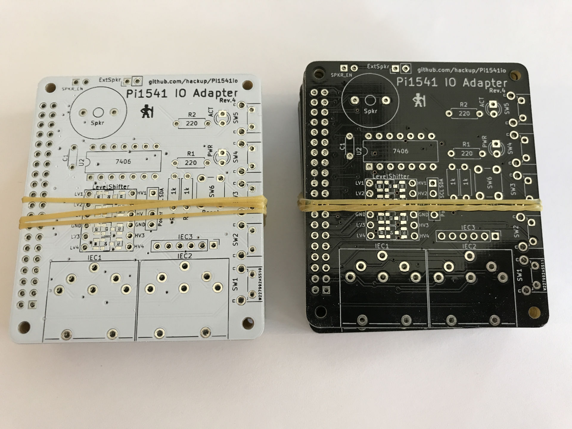
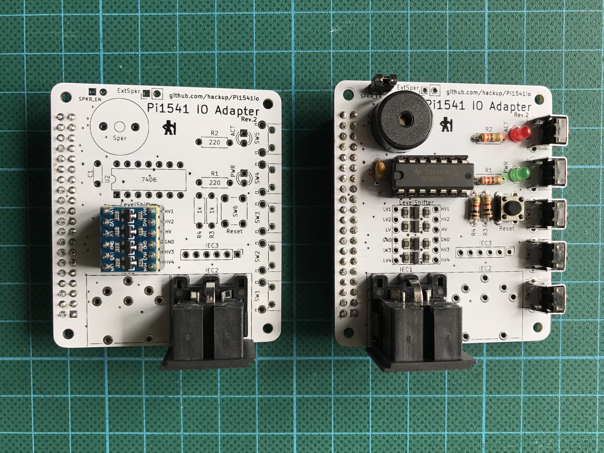
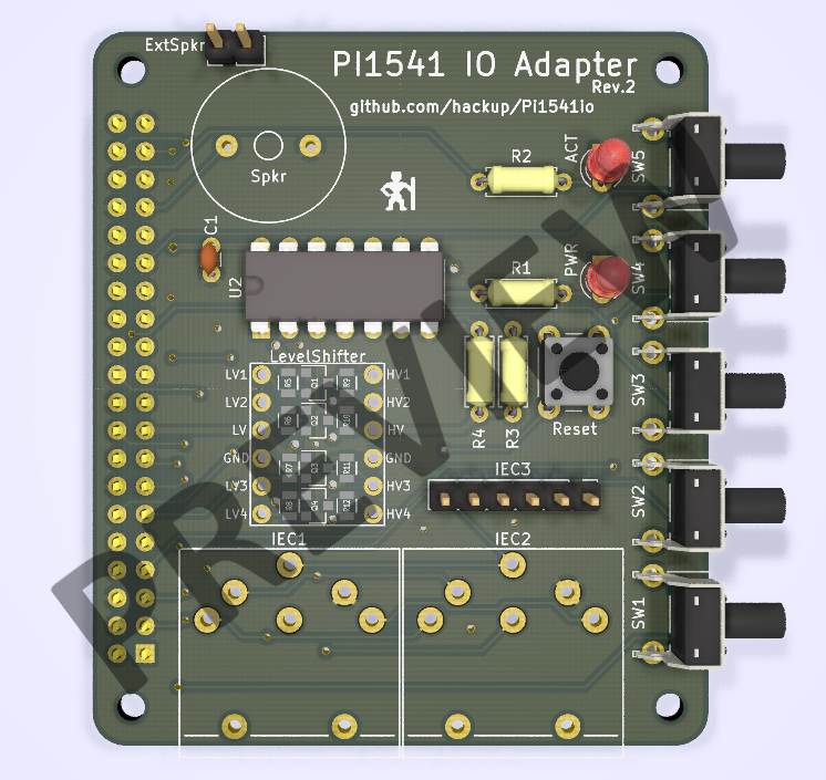
Preview of the current design for revision 2.

So, I ditched the TXS0108 and I am working to support Steve’s 7406 based solution in revision 2 of the Pi1541io. This support will be optional, i.e. you will still be able to use the board with just the level shifter. Speaking of the level shifter: also in revision 2, you may now chose between using a ready made module like in revision 1 or using discrete components instead.

Also, I am still preparing the project repository for upload to Github. Should happen soon now, stay tuned.

Pi1541 IO Adapter

Update 2018-05-25: Now that revision 1 is confirmed to be working despite a couple of minor issues, here’s the rev.1 Gerber files for download. Bear in mind though that the improved 2nd revision is under development and will be available soon!

Two weeks ago, there were exciting retro-news on the Lemon64 board: Gorack – aka. Steve White – released the first version of his Pi1541 that he had been working on for quite some time. “Pi1541 is a real-time, cycle exact, Commodore 1541 disk drive emulator that can run on a Raspberry Pi 3B (or 3B+).”

I was curious and wanted to give this a try, but I also wanted proper wiring. So I created my own version of an extension board for the Raspberry Pi. (Not a proper “HAT”, that would require an eeprom and other things.) I then ordered a small prototype batch because others were eager to try our new retro toy, too.

I received the PCBs on Friday after some unfortunate delay at the German customs and by now the first board is assembled and seems to be working fine!

There are two minor issues in revision 1 that I will address in revision 2: Continue reading

Retro Repair, Addendum I

In my last post I repaired the mainboard of an old Commodore 64 I had retrieved from the attic. After replacing quite a few components, the board was working again for most practical purposes. One issue remained to be investigated though: under certain circumstances, some characters on the screen would change their color seemingly at random.

Random characters changing their color.

This was already visible in the diagnostics output but turned up again later in a graphics adventure I tried. Besides the VIC chip itself, the static color RAM U6 or the 4066 quad switch logic IC U16 seem likely causes for this problem. Continue reading