Update 2018-05-25: Now that revision 1 is confirmed to be working despite a couple of minor issues, here’s the rev.1 Gerber files for download. Bear in mind though that the improved 2nd revision is under development and will be available soon!
Two weeks ago, there were exciting retro-news on the Lemon64 board: Gorack – aka. Steve White – released the first version of his Pi1541 that he had been working on for quite some time. “Pi1541 is a real-time, cycle exact, Commodore 1541 disk drive emulator that can run on a Raspberry Pi 3B (or 3B+).”
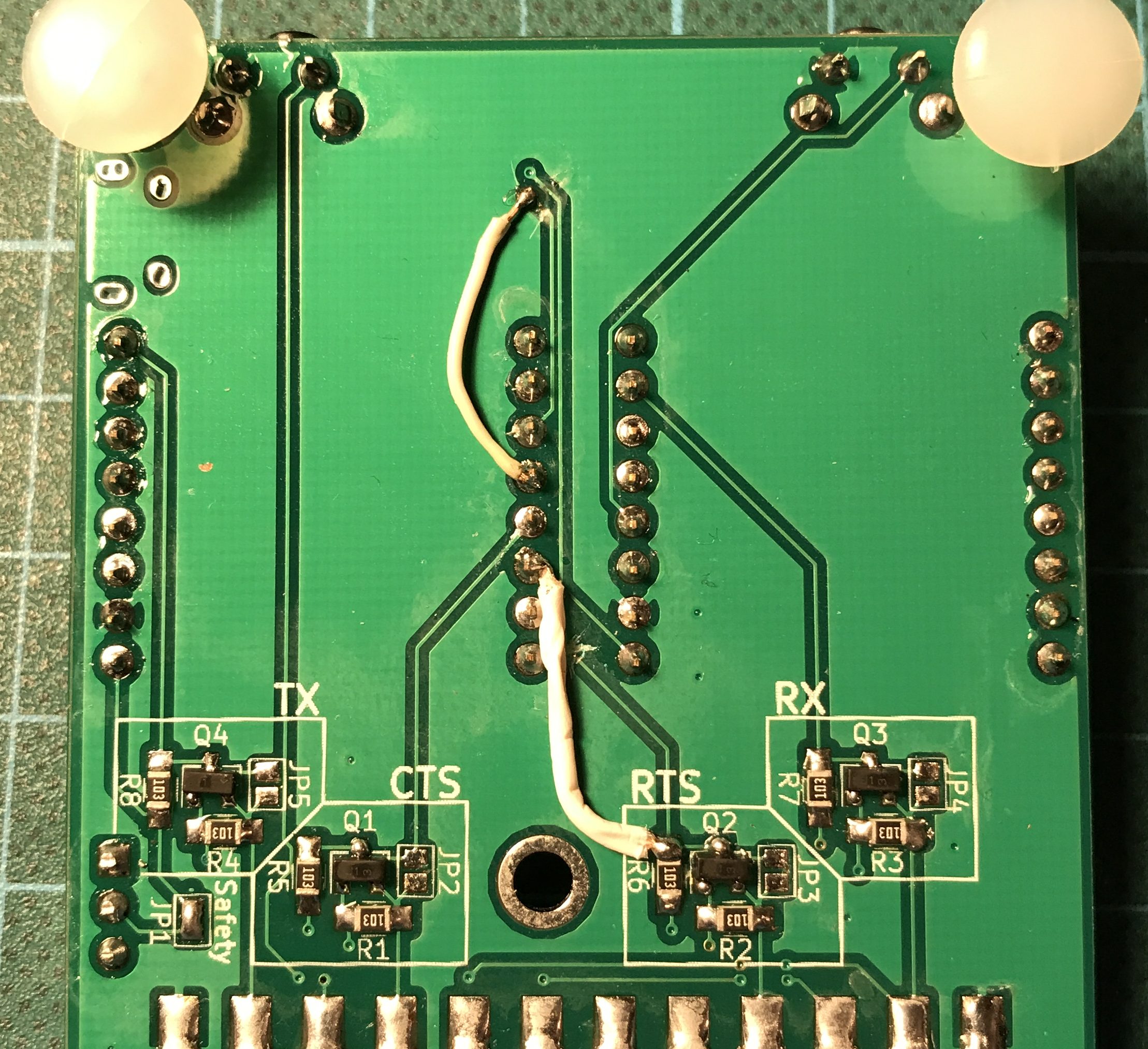
I was curious and wanted to give this a try, but I also wanted proper wiring. So I created my own version of an extension board for the Raspberry Pi. (Not a proper “HAT”, that would require an eeprom and other things.) I then ordered a small prototype batch because others were eager to try our new retro toy, too.
I received the PCBs on Friday after some unfortunate delay at the German customs and by now the first board is assembled and seems to be working fine!

There are two minor issues in revision 1 that I will address in revision 2: Continue reading